TM3217, 3247, 3267
82
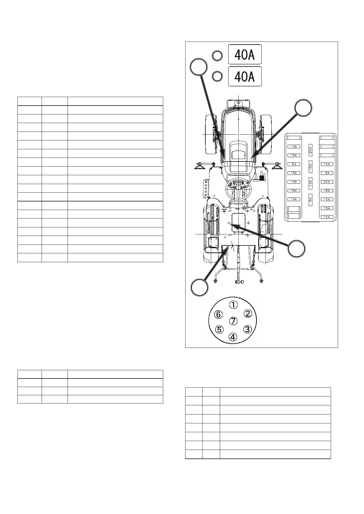
FIG. 147:
General layout and location of electrical sys-
tem components and fuses:
(A) Main Fuse Box
- Located near the rear right-hand
side of engine.
TABLE 8: Function of main fuse box
Ref. Amp Function
1 - -
2 10A PTO (only HST transmission)
3 15A ACC / Working lamp
4 5A Fuel Pump
5 15A ACC / Beacon power supply
6 10A ACC / Power supply for Cabin
7 15A Winker
8 15A Meter Panel, Safety relay
9 - -
10 - -
11 - -
12 10A Starer Relay, Key stop solenoid
13 5A Glow Monitor
14 20A BATT / Cabin power supply
15 15A Head Light
16 10A Light, Horn
17 15A Hazard
18 10A Brake Lamp
(B) Slow Blow Fuses
- Located near the rear left-hand
side of engine.
In-line fuses protect relevant circuit by melting when
sustained heavy electrical load or short circuit is
encountered.
IMPORTANT: Slow blow fuses are of amperage ca-
pacity for the circuit in which they are
located. Use only authorized parts for
replacements.
TABLE 9: Function of slow blow fuse
Ref. Amp Function
B-1 40A Alternator Circuit (Green)
B-2 40A Main Switch (Green)
B-3 40A Starter (Green)
FIG. 147
(C) 7-pin Trailer Socket
- Located in the rear side of
tractor
TABLE 10: Function of 7 pins socket
Ref. DIN Function
L Left-hand side direction indicator lamp
52 -
31 Ground
R Right-hand side direction indicator lamp
58R Right-hand side position lamp
54q Stop lamps for rear combination lamps
58L Left-hand side position lamp
(D) Seat Switch
- Located under the seat
 Loading...