LUBRICATION & PERIODIC MAINTENANCE
75
COOLING SYSTEM
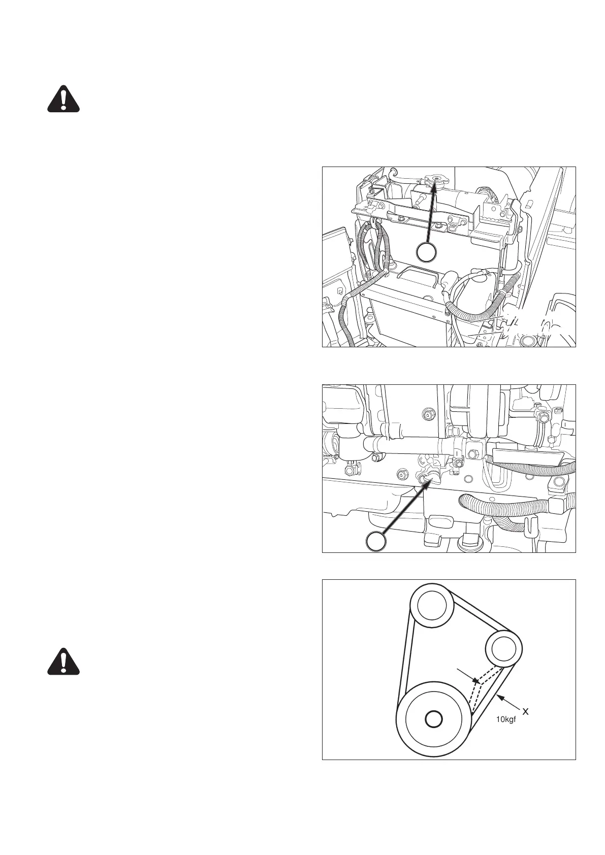
CAUTION: DO NOT remove the radiator cap
(1) when the engine is hot. After engine has
cooled down, rotate the cap slowly to re-
lease pressure. Then the cap can be safety
removed.
FIG. 135:
Cooling system is filled at factory with anti-
freeze solution to protect the engine and radiator to
-34 °C (-30 °F). Cooling level should be maintained be-
tween upper level and under level of reserve tank. Check
coolant annually as a precaution against freezing.
NOTE: After adding coolant, start the engine and let
it run until thoroughly warmed so coolant is
mixed.
Periodically check the condition of hoses, belt and
champs and tighten or replace as necessary.
Keep the radiator, radiator screen and hood screens
clean to permit maximum cooling.
IMPORTANT: Use care when cleaning the radiator to
prevent cooling fin damage.
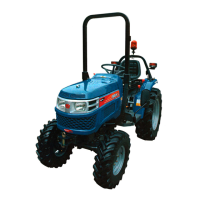
FIG. 136:
Drain cock (2) will drain coolant from the cylin-
der block and radiator. The drain cock is located on the
right side of the engine. Coolant should be replaced if it
becomes contaminated with rust or sludge. Loosening
the radiator cap will assist draining.
NOTE: Before adding new coolant, flush inside of the
radiator and engine block with clean water.
The radiator and engine must be drained if freezing
temperatures are expected and the cooling system is not
filled with sufficient to provide adequate protection from
freezing.
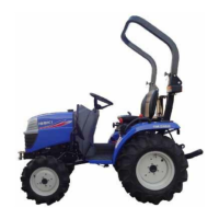
FIG. 137:
Correct fan belt tension helps to insure ad-
equate coolant flow through the cylinder block and radia-
tor. The belt is correctly tensioned when belt deflection
is approximately 12 mm (1 / 2”) as shown at “x” when
thump pressure is exerted at the center of belt span.
CAUTION: Due to muffler position, allow it
to cool before checking or adjusting fan belt
tension.
FIG. 135
FIG. 136
FIG. 137


 To Next Page