T
he
reference
in
surface
TreaTmenT
International
Surface
T
echnologies
istsurface.com
28
DCM600 to 1800 - Instruction Manual
1.1 — Requirements for feeding matter
The controller has a power «universal» power that connects input power of 120 V AC to 240 V AC. The input
voltage must be between 85 and 270 V AC / 50 Hz or 60 No change in circuit is required when switching between
these tensions. The values of solenoid, however, must be adjusted to accommodate the voltage of the selected
line.
1.2 — Terminal connections of the DCT1000
Line solenoid valve and connections are located on the lower edge of the map below the plastic. The terminal
block is a connector type «Euro» that grips the wire into the connector body. The connector accepts wires from
14 to 22 AWG. The wire should not be stripped of more than 0.25 inches to avoid short circuit or expose bare son
creating a potential hazard of electric shock.
To help you determine the right to bare wire lengthways required a mark length of wire stripper is provided in the
lower right corner of the map. The connector system used on the DCT1000 is specied for a single connection,
but you can splice several together if local codes permit and that the practices of performance are met.
To power the master controller and extensionner dr channels, the supply must be connected to line L1 and L2
(see dimensional specications, Figure 1). Connect the solenoid between the selected output and the common
solenoids. The common solenoid and L2 are connected internally.
The contacts of the switches connected to the control inputs at the top of the table above should be isolated
and only connected to the appropriate terminal and common terminals.
The following sections describe connections to external switch. See Figure 2 for the connection of the switch.
1.2.1 Connection of external pressure
The controller can be used with a limit switch or external pressure sensor to provide the cleaning process the
request. The high limit and low limit inputs can be used for this purpose. A simple on-o can be established
with a single pressure switch connected to the input of the upper limit. Better control can be achieved with a
limit gauge high and low as the Photohelic Dwyer ®. In this mode of application, time, free time, and the delay
of the cycle can be programmed to set the cleaning cycle. A three-pin terminal block (TB3) to connect the
outside running up and down (see Figure 2 on next page). These switches should be isolated from contacts.
The common line should not be grounded or protective equipment on the ground because they can introduce
electrical noise and cause a malfunction or possible damage to the sequencer. The operations of these entries
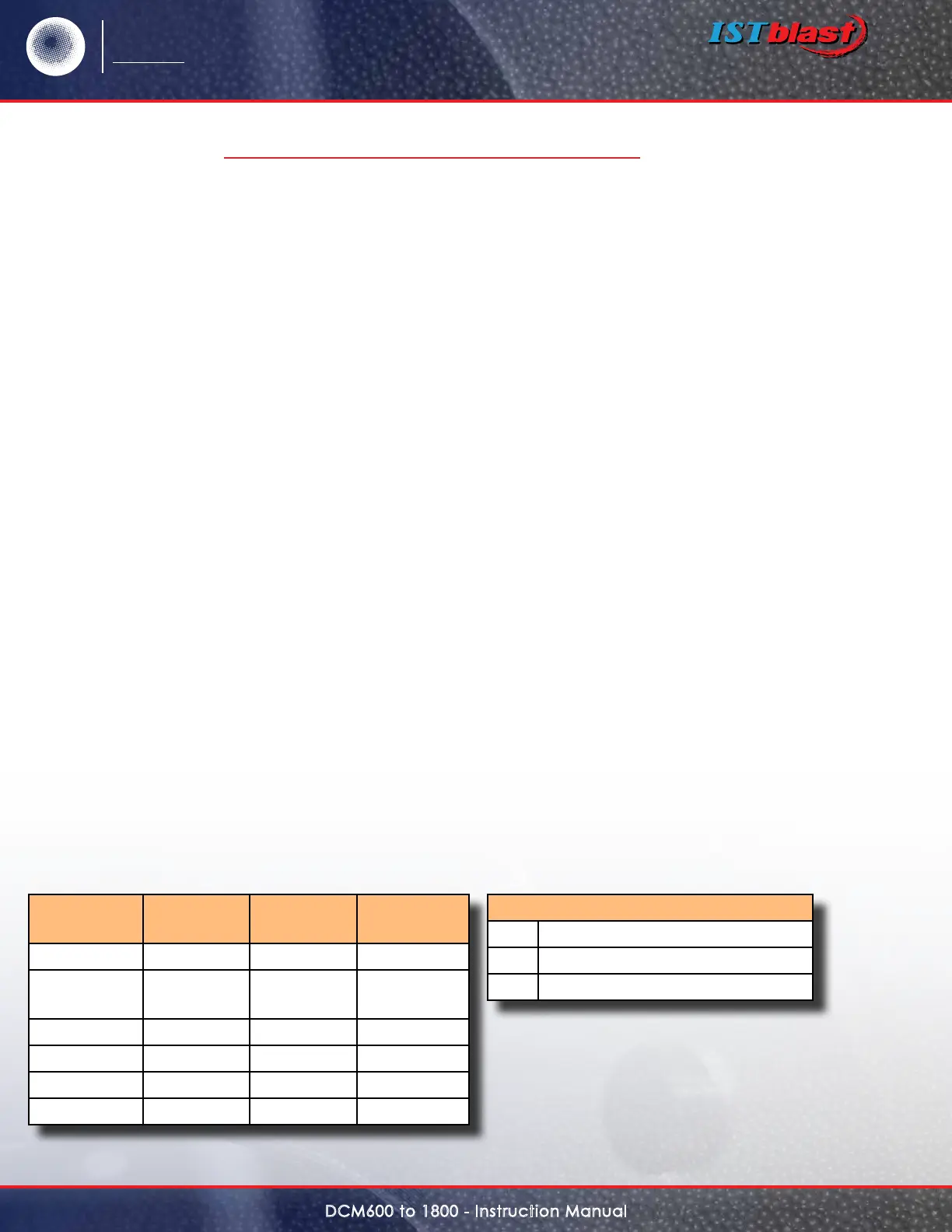
are as follows (see next page):
Operation
in progress
Switch
lower limit
Switch
upper limit
Next
operation
Waiting Open Open Waiting
Waiting or
pending
X Closed In progress
Waiting Ø Open Waiting
Waiting Closed Ø In progress
Run Closed
ß
In progress
Hold Closed Ø In progresss
Legend
X Is open or closed
Ø Transition from open to closed
ß
Transition from closed to open
1.0 INSTALLING THE DCT1000 CONT’D