T
he
reference
in
surface
TreaTmenT
International
Surface
T
echnologies
istsurface.com
40
DCM600 to 1800 - Instruction Manual
1.0 INSTALLATION
Caution : Prior to installing the DCP100A/200A please review the operating specications carefully.
Some operating systems, especially in pneumatic conveying applications, may see static pressure or
vacuum conditions that exceed the capability of the DCP100A/200A pressure module. For these
conditions there are a number of alternate Dwyer pressure products that can be used to meet your application
requirements, all of which can be terminated to the Dwyer DCT1000 Dust Collector Timer Controller. For more
information on these and other Dwyer products, please call us at (219) 879-8000, or visit us on the web at www.
dwyer-inst.com or www.dust-controls.com
1.1 — Location
The system should be located in an enclosure that meets relevant safety standards and electrical codes. There
are no other special orientation requirements as the pressure module is not orientation sensitive. Care should
be observed when routing the air hoses to ensure that any potential condensation or moisture will not drain
into the sensor. Where heavy condensation is present,a drip loop or an in-line lter should be installed to ensure
long term operation.
1.2 — Connections
When a pressure module is installed, the 4- 20 mA process signal and the alarm relay contacts are available. The
circuit may be used with the internal 24 V power source or with an external source. In either case,the 4-20 mA
circuit is isolated from ground and other signals.
The alarm relay contacts are isolated, normally open contacts. Pressure connections may be made to the
stepped hose barbs with either 1/8’’ or 3/16’’ I.D. tubing. The following subparagraphs describe the external
switch connections. Refer to Figure 1 (above) for switch connection illustration.
1.3 — Pressure Module Installation
The pressure module is attached to the Master Controller using integral connectors on both units. The
insertion ports for the pressure module are located in the upper left quadrant of the DCT1000 Master
Controller. The pressure module can be removed by compressing the retaining clips on each end of the
module, then gently pulling the module out of the master controller board. When inserting the module,
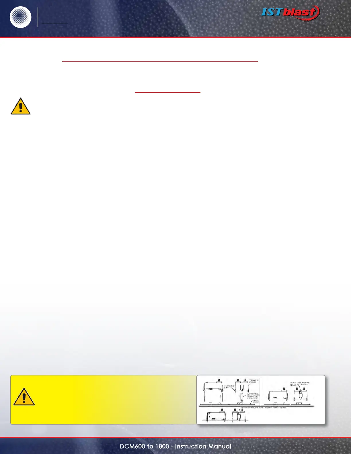
the following procedure should be adhered to insure proper installation:
•Examinethebottomofthepressuremoduleandnotetheorientationoftheconnectors.
•Alignthemodulesothattheseconnectorsmatch the connector receptacles on the controller board.
•Orientthemodulewiththefouralignmentpinsovertheirrespectivemountingholes.
•Gentlypressthemoduleintotheconnectorsandsnaptheretainingclipsoneitherendofthemoduleinto
their slots.
•Alwaysinstallandservicethisdevicewiththepoweroandalockoutinstalledifrequired.“Hot”pluggingthe
pressure module into an operating system may damage the system or cause the calibration parameters to be
erased.
Caution : Do not force the module into the
connectors. Forcing the insertion may damage the
connectors. Properly aligned, the module should
snap into place.
SERIES DCP100A/200A PRESSURE MODULESCONT’D
SPECIFICATIONS – INSTALLATION & OPERATING INSTRUCTIONS