NOMENCLATURE AND FUCTIONS
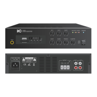
33.MIC 1 PRIORITY SWITCH
When selected, these switches will give prio-
rity to channels 1 over all other channels in-
puts.
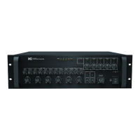
34.4 hms\8 hms 70V\100V SPEAKER OUT-
PUT TERMINAL
This terminal is for speaker wire connection.
connect speakers whose combined impeda-
nce is equal to or higher than the rated output
impedance, as shown below.
35.(CH1~CH5)ZONE SPEAKER OUTPUT
36.POWER SWITCH
This switch turns the phantom power supply
on or off for all channels. When the switch is
turned on,+24V DC power is supplied to pins
2 and 3 of each channel's input connector.
Use phantom power when connecting cond-
enser microphones, which require an external
power supply.
37.~220-240V 50/60HZ POWER INPUT
Pin 1: Remote amplifier input signal hot(+)
Pin 2: Remote amplifier input signal cold(-)
Pin 3: Signal ground
Pin 4: Remote control 1(Speaker 1)
Pin 5: Remote control 2(Speaker 2)
Pin 6: Remote control 3(Speaker 3)
Pin 7: Remote control 4(Speaker 4)
Pin 8: Remote control 5(Speaker 5)
Pin 9: Remote control ground
Pin 10: DC +24V
Pin 11: Input Chime
Pin 12: NC
Pin 13: NC
Pin 14, 15: NC
7
 Loading...