Power Supply Function
The interface returns to the main interface of the system and displays
STARTING-PROFILE.
7. Press [On/Off] on the front panel to turn on the output.
8. According to the selected trigger method (same as the trigger method of the
LIST function), for example, press [Shift]+[On/Off](Trigger) to trigger the
output of the waveform.
Load Dump Dynamic Behavior
This test is a simulation of load dump transient occurring in the event of a dis-
charged battery being disconnected while the alternator is generating charging
current with other loads remaining on the alternator circuit at this moment.
• The amplitude of load dump is determined by the rotational speed of alterna-
tor and the strength of magnetic field in the case of disconnection of the
battery.
• The pulse duration of load dump is mainly determined by the time constant
and pulse amplitude of the excitation circuit.
Inside most novel alternator, the amplitude of load dump is decreased by in-
creasing the limiter diode (clamping diode). The load dump may be caused by
cable corrosion, poor cable contact or disconnecting the battery intentionly
when the engine is running.
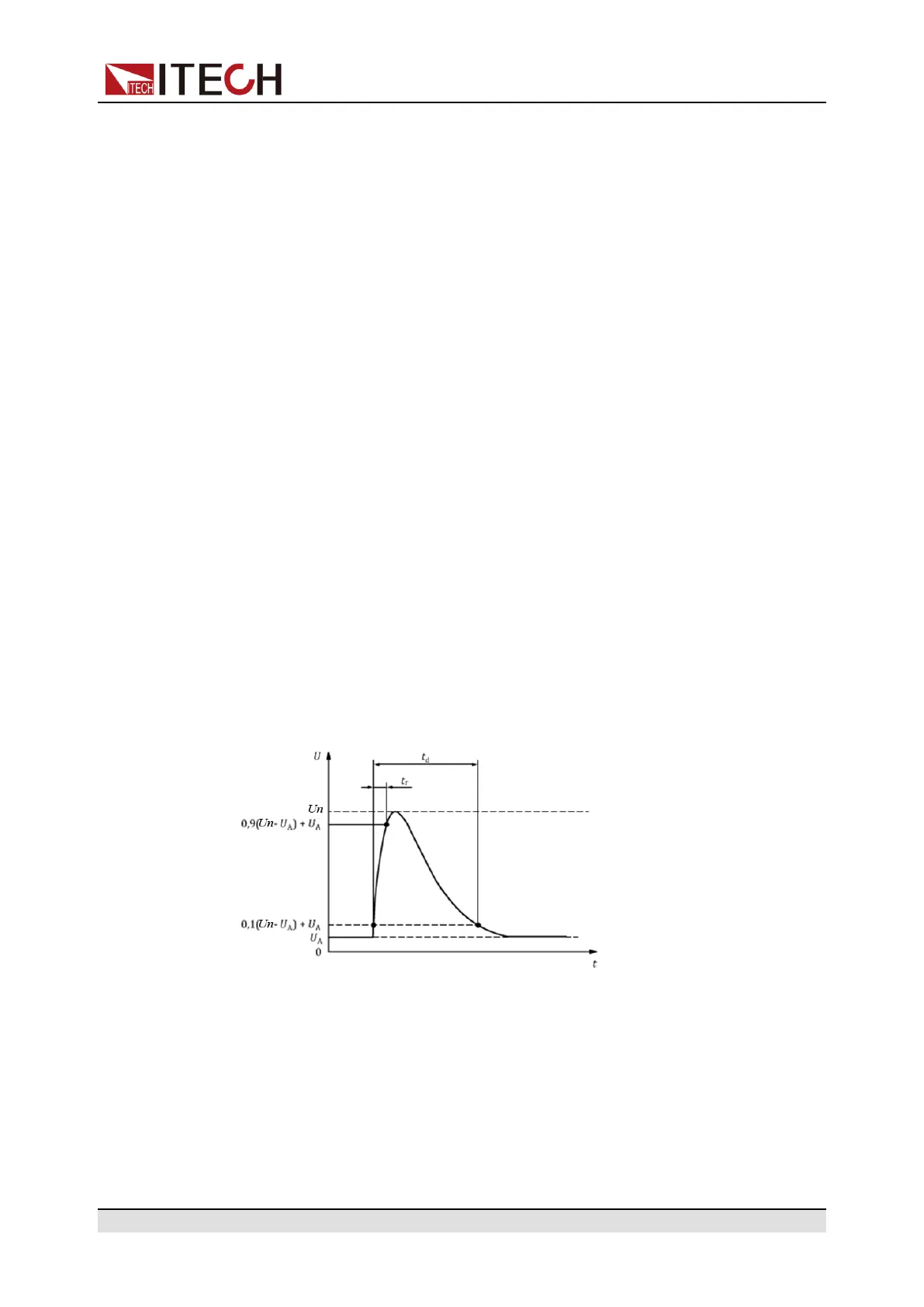
The pulse shape and parameters for an alternator without centralized load
dump suppression (Test A) are given in follow.
• t: Time
• U: Voltage
• t
d
: Duration of pulse
• t
r
: Rising Slope
• U
A
: The supply voltage of the generator in operation: U
A
= 14V in the 12V
system, U
A
= 28V in the 24V system. (see ISO 16750-1)
Copyright © Itech Electronic Co., Ltd.
95