Quick Reference
Copyright © ITECH Electronics Co., Ltd. 12
Set the range of the mΩ Meter to 10W
Generate programs in List Mode
Check the information of the power supply
2.5 Function description of VFD status indicators
IT6100B series power supply VFD indicator lamps description as follows:
OVP function is triggered.
Matching address when
communicate by GPIB
Power supply is in GPIB
serial polling request mode
Waiting for a trigger signal
2.6 Power-on self-test
A successful self-test indicates that the purchased power product meets delivery
standards and is available for normal usage.
Before operation, please confirm that you have fully understood the safety
instructions.
To avoid burning out, be sure to confirm that power voltage matches with
supply voltage.
Be sure to connect the main power socket to the power outlet of protective
grounding. Do not use terminal board without protective grounding. Before
operation, be sure that the power supply is well grounded.
To avoid burning out, pay attention to marks of positive and negative polarities
before wiring.
Self-test steps
Normal self-test procedures:
1. Correctly connect the power cord. Press Power key to start up.
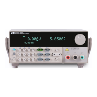
2. After self-test, if the power supply is normal, then VFD will display the output
voltage and current status as below:
OFF
0.000V 0.0000A
0.0001V