Installation
Copyright ©ITECH Electronic Co., Ltd. 20
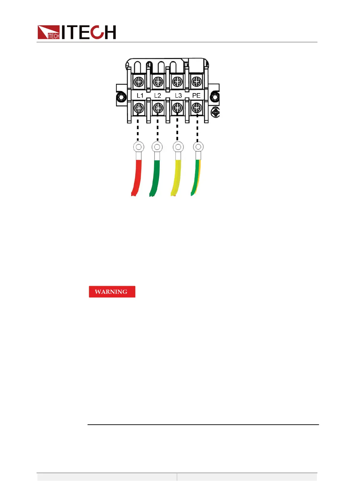
protective grounding terminal (PE).
5. Mount the protective cover back to its original position.
6. Refer to the suggestion connection diagram, connect the other end of the
power cable to the required AC distribution box.
3.2 Connecting Test Lines ( Optional)
Test lines are not standard accessories of the instrument. Please select optional
red and black test lines for individual sales based on the maximum current value.
For specifications of test lines and maximum current values, refer to
“Specifications of Red and Black Test Lines” in “Appendix”.
z Before connecting test lines, be sure to switch off the instrument.
Power switch is in Off position. Otherwise, contact with output
terminals in rear panel may cause electrical shock.
z To avoid electrical shock, before testing, please make sure the
rating values of the testing lines, and do not measure the current
that higher than the rating value. All test lines shall be capable of
withstanding the maximum short circuit output current of the power
supply without causing overheat.
z If several loads are provided, each pair of load wires shall safely
withstand the rated short circuit output current of the power supply
under full load.
z Always use test lines provided by ITECH to connect the equipment.
If test lines from other factories are used, please check that the test
line can withstand maximum current.
Specification for Test Cables
Test cables are not standard accessories for the instrument. Please select
optional red and black test cables for individual sales based on the maximum
 Loading...