Do you have a question about the ITech IT7900 Series and is the answer not in the manual?
Introduces the IT7900 series power supply, its capabilities, and applications.
Details the available IT7900 series models, their power, voltage, current, and phase specifications.
Lists and describes optional accessories like GPIB, RS-232/Analog, and fiber optic cables for expansion.
Provides dimensions and installation space considerations for the IT7900 series power supply.
Instructions for checking package contents and reporting any discrepancies or damage.
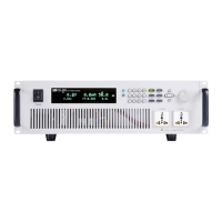
Identifies and describes the components and controls located on the front panel of the IT7900.
Explains the functions of each key on the IT7900 power supply's keyboard interface.
Details the functionality of the push-on knob for value setting and menu selection.
Identifies and describes the connectors and ports on the rear panel of the IT7900 series.
Provides safety precautions and steps for connecting the power cord to the instrument.
Guides on selecting and connecting optional test lines for instrument testing.
Explains the procedures and safety precautions for powering on the instrument.
Describes the IT7900's touch screen interface and display for single and three-phase modes.
Introduces the touch screen interface, drag-and-drop functions, and menu navigation.
Details how to program voltage and frequency values using keys or the knob.
Explains how to use the [On/Off] key to control the power supply's output status.
Describes the 4-Quadrant grid simulator and power amplifier capabilities of the IT7900.
Guides on selecting between single-phase, three-phase, reverse phase, and multi-channel modes.
Explains the AC, DC, AC+DC, and DC+AC output modes available for the IT7900.
Details the Constant Voltage (CV), Constant Current (CC), and Constant Power (CP) modes.
Describes the anti-islanding test mode for inverter and grid-tied DUT testing.
Covers how to select standard and user-defined waveforms for output.
Explains the power amplifier function for hardware-in-the-loop applications.
Describes the auto-ranging capability for voltage and current at fixed power.
Details how to simulate AC grid impedance using programmable output impedance.
Explains how to use the Sweep function to test efficiency and capture parameters.
Provides a reference to the system menu options for configuration and settings.
Explains how to enable and disable the keyboard lock feature.
Details how to switch between local and remote control modes.
Guides on saving and recalling instrument parameters using nonvolatile memory.
Covers overcurrent, voltage limit, and over-temperature protection settings.
Describes how to capture and save the instrument's screen to a USB disk.
Explains the different trigger sources available for controlling operations.
Details how to connect multiple units in parallel for increased power output.
Explains how to use remote sensing for maximizing measurement accuracy.
Covers the digital input/output functions for logic control and status indication.
Describes the optional analog interface for external control and monitoring.
Explains the basic metering functions and parameters displayed on the interface.
Details how to display and analyze voltage and current waveforms using the oscilloscope function.
Covers the harmonic analysis capabilities, including list and bar chart displays.
Guides on creating and managing list files for AC wave sequences with varying amplitudes.
Explains how to simulate surge and sag for voltage fluctuation testing.
Describes how to create and edit custom waveforms for use in list operations.
Lists the detailed technical specifications, including input/output parameters and ranges.
Provides information on calibration frequency and cooling style.
Explains how to connect and use the USB interface for PC communication and control.
Details the configuration and use of the LAN interface for network connectivity.
Covers the configuration and troubleshooting of the CAN communication interface.
Describes the optional GPIB interface for instrument control and communication.
Explains the optional RS-232 interface for serial communication.
Lists common SCPI commands for remote operation and control.
Introduces computer control software for remote operation and testing.
Lists specifications and current ratings for optional test lines.
| Brand | ITech |
|---|---|
| Model | IT7900 Series |
| Category | Power Supply |
| Language | English |