Inspection and Installation
Copyright ©ITECH Electronic Co., Ltd. 75
3.
Select CAN and press [Enter].
4.
Set the baud rate and address, press [Enter].
CAN Troubleshooting
If you meet some problems when communicating with PC by CAN interface, please
check the following items:
•
PC and the instrument must have the same baud rate.
•
Ensure you have used the correct communication cable (CAN_H, CAN_L).
Please pay attention that some cable may not have a correct internal wiring
even it is with an appropriate plug.
•
The interface cable is correctly connected (CAN_H to CAN_H, CAN_L to
CAN_L).
•
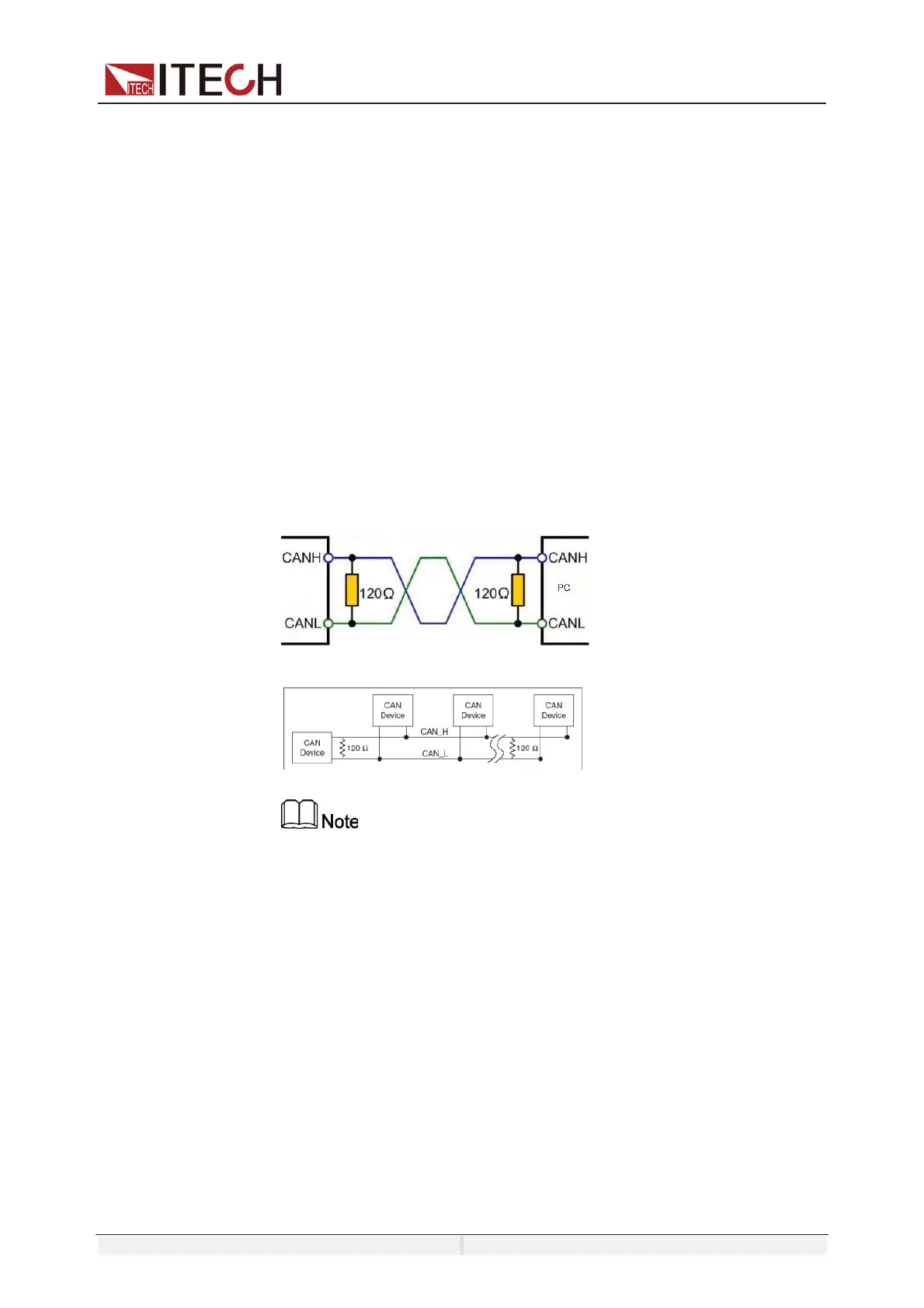
If the communication signal is poor or unstable, it is recommended to
con- nect a 120 Ω terminating resistance.
–
The connection diagram of a single device is as below.
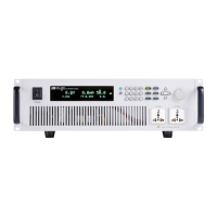
–
The connection diagram of multiple devices is as below.
When multiple devices are connected, it is recommended to
connect the pin 8 (GND) of the P-IO terminal on the rear panel of
these devi- ces in parallel, and the communication quality will be
improved in the entire CAN network.
10.4 GPIB Interface (Optional)
The GPIB (IEEE-488) interface is assembled in the IT-E176 communication board.
Use a GPIB cable to connect GPIB interfaces of the instrument and PC. Please ensure
that the screws have been screwed down in order to have a full connection.
GPIB Configuration
Each device on the GPIB (IEEE-488) interface must have a unique whole num- ber
address between 1 and 30. Your computer’s GPIB interface card address must not