Installation
Copyright ©ITECH Electronic Co., Ltd. 23
5. (Optional) According to the actual situation of DUT, connect the grounding
terminal on the rear panel of the instrument to the DUT to ensure the safe
grounding.
For the location information, see 1.5 Rear Panel Introduction.
6. Connect the other end of the red and black cables to the DUT. The positive
and negative poles must be properly connected and fastened when wiring.
Connecting the DUT (Remote Sensing)
Remote measurement is available for the following scenarios:
When the DUT consumes large current or the wires are too long, there is a
voltage drop on the wires between DUT and output terminals of the power
system.
To maximize measurement accuracy, the power system provides the remote
measurement terminals VS+ and VS- on the rear panel, which can be used to
measure the terminal voltage of the DUT.
When the power system is used for battery testing in actual applications, the
voltage drop of the wire will lead to voltage inconsistency of both ends and
inconsistency of the cutoff voltage of power system and the actual voltage of
battery, resulting in inaccurate measurement.
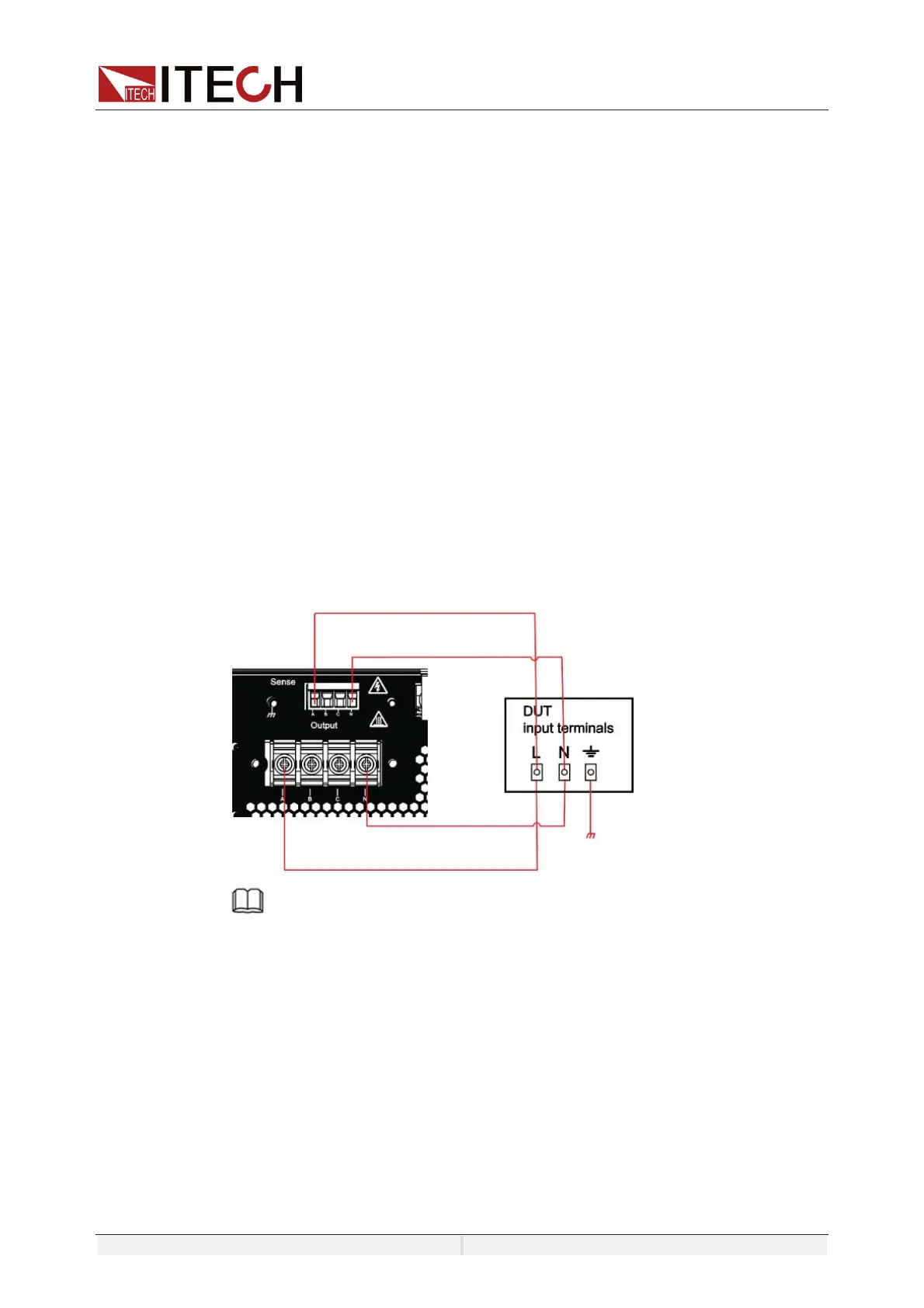
The connection diagram and steps of remote measurement are as follows:
z The connection diagram of single phase is shown as follow:
NOTE
When the output voltage has DC voltage, the output terminal L is positive, and N is
negative.
 Loading...