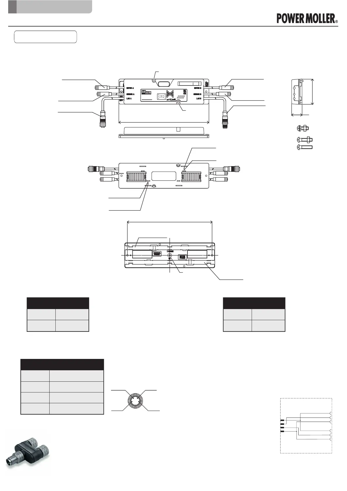
1.3 Connectors for IB
・
Input for sensor and sensor alarm is fixed to PNP input.
・
The setting for “Dark ON” or “Light ON” can be switched with iCEP or PLC.
【
Control Power
】:
As-i pin
【
Motor power
】:
As-i pin
【
Sensor cable
】:
M8-4pin connector (female) Cable length 260mm
No For
1 +24V
20V
・
Use As-i cable for power cable.
○ Mounting a driver Card
○ Mounting Base
・
Use As-i cable for power cable.
1 +24V
2 Sensor alarm
3GND
4 Alarm signal
No For
No For
1 +24V
20V
4
Black
3
Blue
1
Brown
2
White
LED412
LED410
LED409
LED407
LED406
LED405
LED403
LED401
LED400
16
Ver.1407/ 9906
IB-P05F-P
MAC:00-22-21-XX-XX-XX
BF
SF
ACT BLAN B
POWER
SEN BMOT BSTS B
SEN AMOT ASTS A
ACT ALAN A
65
27
233
IB-P05F-P
Hole for cover fixing
(M4×16)
Hole for cover fixing
Hole for cover fixing
(M4×16)
CN305:
Sensor cable
CN201:
Motor cable
CN402::
LAN cable
R
CN101:
Motor cable
CN304:
Sensor cable
CN401:
LAN cable
L
Control power:
As-i pin 2
Control power:
As-i pin 1
Motor power:
As-i pin 1
Motor power:
As-i pin 2
*Accessories
M4x16 screw set: 2 sets
M4x12 screw set: 2 sets
(For base fixing)
M4x16 screw: 2pcs
219:Mounting hole position(Driver) - M4×16
Mounting hole
posion(Base)
- M4×12
Motor Power
upper:0V
lower:+24V
Control Power
upper:+24V
lower:0V
1
4
2
3
1
4
3
1
4
3
S1
S2
Connection of 2 sensors is possible by
using M8 4pins to 2 x M8 3 pins adaptors
such as SAI Y-4S M8-M8 (Weidmüller).
So, Alarm signal will be the second sensor
signal.
• With iCEP: Refer to «iCEP User Manual»
• With PLC: Refer to «Connection with
PROFINET capable PLC» user manual -
Paragraph 5 «How to change parameters».
• Ensure that sensor current consumption
doesn’t exceed 1.1 A (Sensor A + Sensor
B)
Original notice - A1.2
9
Connectors for IB
IB-P05 Technical documentation
1. Introduction
 Loading...