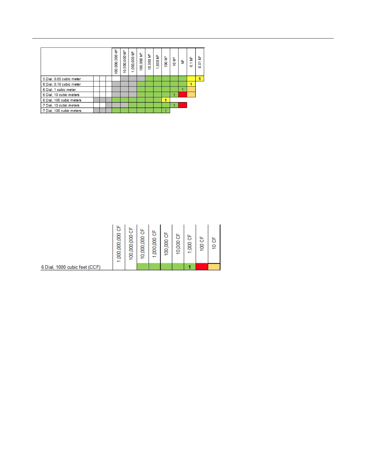
Programming example: Endpoint programmed for 6 dial, 1000 cubic feet CCF.
1. Enter the initial index read. For this example, the initial read is 123456 where 6 = 600
cubic feet. After the initial programming, an endpoint read will result in a reading of
1234560 where the least significant digit is in 10's of cubic feet. Since counting is with a
drive rate of 1000 cubic feet and the reading is transmitted in 10's of cubic feet, the last
two digits of the reading will not change.
2. Program the endpoint to 123456.
3. Read the endpoint. The result should be 1234560 with the zero added to put the reading
in 10's of cubic feet.
4. Add one count. The result should be 1234660. Notice that the last two digits of 60 do not
change.
Mercury X-Blank options
Endpoints (ERT modules) can be programmed with one of the Mercury X-Blank options.
There are 1, 2, 3, and 4 blank option available. Blank options are set up as a what-you-see-
is-what-you-get (WYSIWYG) configuration. The values are not set in cubic feet or cubic
meter standards. The Mercury X-Blank options are used in configurations where the system
receives pulses from a corrector or instrument that can change pulse values and has
configurable display digits. The Mercury-X Blank options allow users to program the
endpoint to match the configuration of the corrector or instrument.
Check Endpoint functions
The FDM Check Endpoint function triggers users to input the number of dials and drive rate
if a Check Endpoint is requested for an endpoint programmed for 5, 6, or 7-dial meter
configurations. The request to input the dial and drive rate information happens only if the
system has more than one option using the same count rate and rollover variable enabled in
their FDM business unit.
100G Series Remote Module Programming
100G Series Gas ERT Module Installation Guide, Remote Mount TDC-0824-017 16
Proprietary and Confidential