Note: Aligning the second bracket threaded hole and drilled hole may require some manipulation of
the mounting bracket.
11. Insert the module cables (both units) through the large cable strain relief on the left rear of the
instrument's enclosure. Leave a one-half to one inch drip loop under the cable strain relief.
12. Secure three cable ties on the module cables in three places on the cables as specified by
information included in the kit.
13. Re-install the input switchboard, main board, and battery pack removed in step 2.
Honeywell mechanical and wiring installation instructions
This section includes the information to wire two ERT modules to a single Honeywell
Instrument. Installation requires the correct programming parameters (for programming
parameters, see Programming the Honeywell Instrument parameters on page 50).
Connecting the remote ERT modules to a Honeywell Mini-AT,
Mini-Max, or EC-AT
With Itron 100G remote ERT modules, utilities can receive corrected and uncorrected
consumption values by installing two ERT modules. The ERT module for corrected reads is
attached to the corrector's pulse output. The ERT module for uncorrected reads is attached
to the input switch board. The corrected pulse output is programmable; the uncorrected
pulse output is dependent on the connected meter's drive rate.
Important: Some Honeywell Instruments have two pulse outputs so the uncorrected pulse
output could be connected to the additional output, but the connection should be to the input
switch board in case the corrector battery fails. Counts will be collected if the uncorrected
pulse is connected to the switch board since the board is not dependent on battery power.
This installation procedure requires a Honeywell mounting kit (Honeywell part number
22-1077). The illustrations show connection to a Honeywell Mini-AT. Connection to the
Honeywell EC-AT and Mini-AT are similar to these instructions. See Honeywell product
documentation for more information.
1. Connect the corrected module wires to TB1 on the Mini-Max board following the Corrected ERT
module connection information. Use Honeywell upgrade kit 40-2678-1 to provide the second pulse
output channel for the uncorrected endpoint.
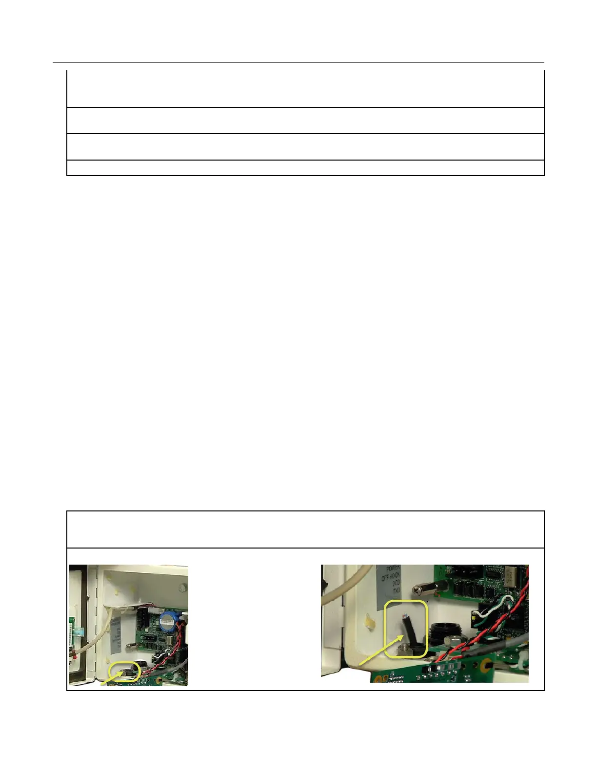
2. Insert the remote ERT module cable into the instrument's compression connector.
Specific Meter Manufacturer Installation
100G Series Gas ERT Module Installation Guide, Remote Mount TDC-0824-017 45
Proprietary and Confidential