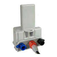
3. Strip one inch of the outer insulation from the cable.
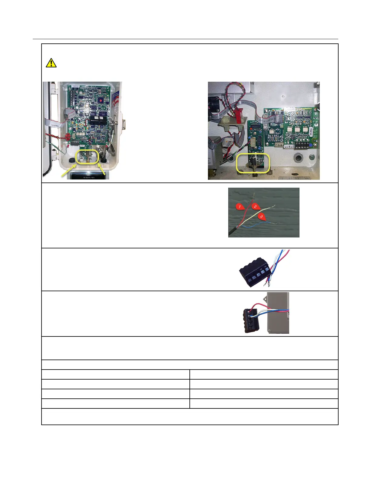
Warning: Keep wires away from the rotating magnetic spindle in the Honeywell
Instrument.
4. Strip ¼-inch individual wire insulation from the
red, white, and blue lead wires.
1. Count enabling wire (pulsed ground
reference)
2. Count sensing wire (high impedance positive
reference)
3. Cut cable sensing wire (positive return)
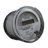
5. Twist the blue and white wires together and
connect them to the Honeywell Instrument
terminal strip connector (Phoenix connector)
following the Honeywell Instrument Item Code
Settings.
6. Connect the red wire following the Item Code
Settings.
Note: In Honeywell Instrument EC-AT correctors, the connector may be soldered to the pulse
board.
Corrected ERT module connections
Mini-Max TB1 ERT module wire color
K terminal Red
Ya terminal Blue*
Ya terminal White*
*Twist the blue and white ERT module wires together before connecting them to the Mini-Max
board. Tighten the terminal connection securely.
Specific Meter Manufacturer Installation
100G Series Gas ERT Module Installation Guide, Remote Mount TDC-0824-017 46
Proprietary and Confidential