Operation: Base Metrology
CENTRON Meter Technical Reference Guide 3-3
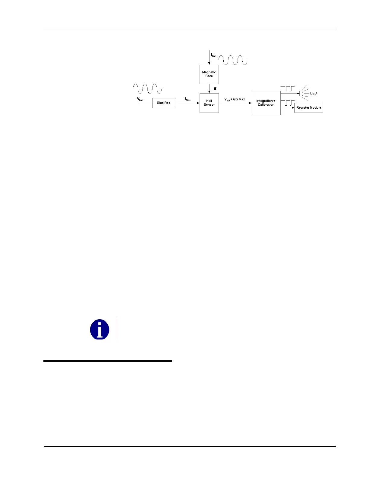
Figure 3.2 Simplified CENTRON Architecture
The custom ASIC cancels all the offset generated by the meter and removes the
need for a light load adjustment of the metrology. This allows the meter to have
excellent accuracy over a very large dynamic range, especially at the low current
levels. For this reason, no offset adjustment is needed or provided for the
CENTRON meter.
There is a slight phase shift in the current to flux density conversion due to eddy
currents in the magnetic core material. This shift causes a small power factor error
that is uniform across the dynamic range (load curve) of the meter. Itron
compensates for this shift in the CENTRON by the use of a capacitor in the biasing
current circuit. This correction is permanent.
The custom ASIC provides:
• Wh pulses to drive the Test LED
The same signal is also provided to the electronic register attachments.
• energy direction (sign)
• 60Hz clock signal synchronized with the line voltage (for time keeping)
• pulse that drives the stepper motor for the mechanical register attachment (1
pulse every 10 watthours)
The metrology board, which houses the measurement components described
above, passes the Wh pulse, energy direction, and 60Hz clock signals to the
personality module attached to the meter base. The two line voltages (one is
referred to as meter ground), and power supply references are also supplied for
reference purposes.
CENTRON 2S CL320, 4S, 12/25S
The advanced metering forms of the CENTRON (2S CL320, 4S, and 12/25S) meter
use the same Hall Effect measurement principle that is used in the form 1S, 2S, and
3S metering forms described earlier in this chapter.
The major difference with these metering forms is the presence of two Hall cells,
magnetic cores, and ADCs (see Figure 3.3).
An inherent feature built into the design of each CENTRON ensures that the calibration of the
product is not affected by any electronic board (existing or planned) added to the meter. This is
achieved by a distributed power supply and documented design requirements in the CENTRON
developer’s kit.