26
Note
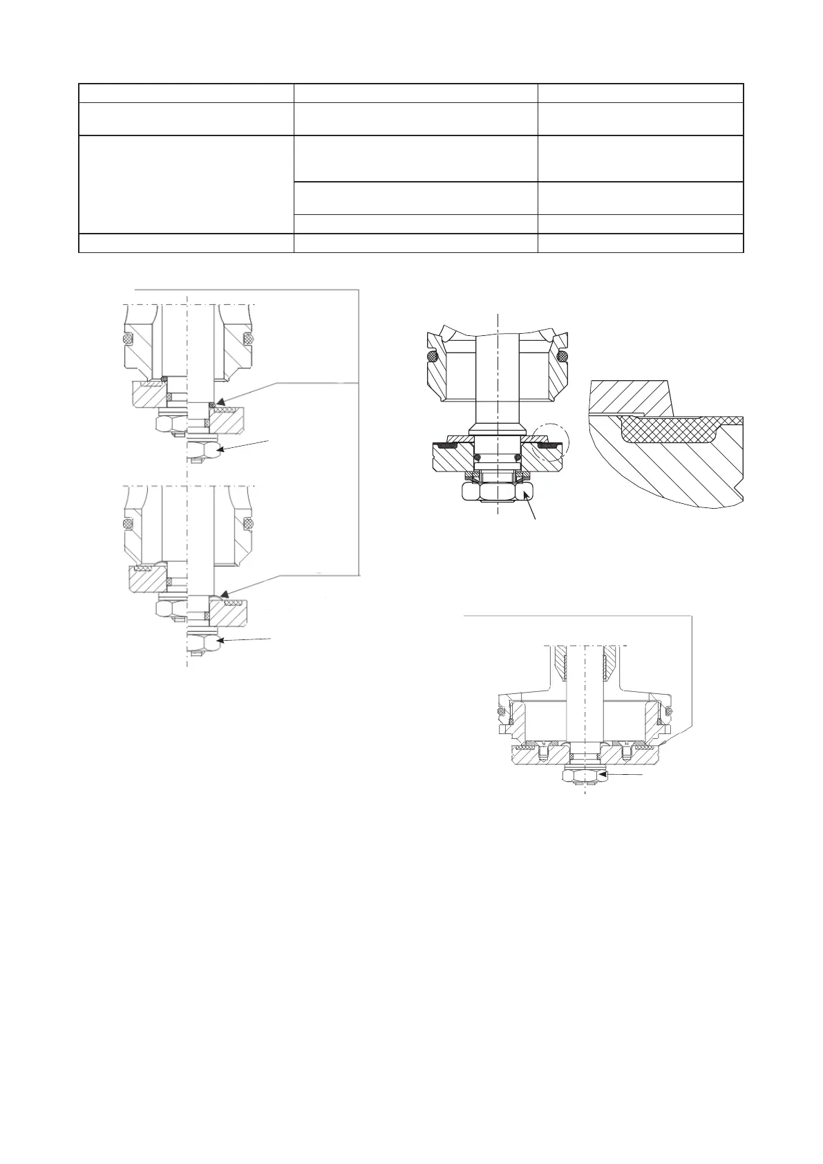
For orifice ø 24 / ø 31 / ø 42, instead of an O-
ring or a compensation disk, install the flow disk
between the valve disk and the collar at the valve
rod.
Remove the O-ring (valve disk seal) before as-
sembling the flow disk and then reinstall it.
The valve disc assemblies are used for orifice
ø 54 & 82. You don‘t need remove the compen-
sation disk.
Standardmodel with
Model with valve disk assy
for orifice Ø54 & Ø82
Model with flow disc
for orifice ø 24 / ø 31 / ø 42
O-Ring
Orifice Ø24
SW 17
Compensation
disc
(Orifice Ø31,
Ø42 and Ø54)
SW 17
SW 17;
SW 19 (DN 80)
SW 17
Flow disc installation.
Remove inspections plate from body (Pos. No 8 of material list). Loosen hex nut; insert a screwdriver
into the slot of the thread to counter hold the valve rod. Remove valve disk, washer and lock washer.
Remove O-ring or compensation disk and install flow disk
(pay attention to correct position!).
Insert valve disk, washer and lock washer. Fasten hex nut (max 5 Nm), counter hold
with a screwdriver (blade: 8 x 1.2or 9 x 1.4 mm).
Reassembling inspections plate on body, check tightness after assembly!
Flow Disc for flow volumes < 10 % of qmax (< 1:10)
DN 25 DN 50 DN 80
Design framework till April 1998
111-163-10 orifice ø 24
Design framework till April 1998
111-163-10 orifice ø 24
Valve disk assy. 111-360-20
orifice ø 54
Design framework from Mai 1998
onwards (recess at the bottom)
111-363-10 orifice ø 24
Design framework from Mai
1998 onwards(recess at the bot-
tom)111-163-10 orifice ø 24
111-363-15 for orifice ø 42
111-163-15 for orifice ø 31
Valve disk assy. 111-560-20
orifice ø 82
111-363-15 for orifice ø 42
111-163-15 orifice ø 31 Valve disk assy. 111-360-20 orifice ø 54
pay attention to
correct position