Mechanical Specifications - Tamp System
Category Nominal Minimum Maximum
Incoming Air Pressure 60 - 100 PSI 40 PSI 125 PSI
Tamp Cylinder Pressure 30 - 50 PSI 20 PSI 80 PSI
Vacuum/Blow Pressure 30 - 60 PSI 20 PSI 80 PSI
Tamp Stroke
(10 in. cylinder)
3 - 9 in.
76 -228 mm.
3 in.
76 mm.
9.5 in.
241.3 mm.
Tamp Stroke
(20 in. cylinder)
3 - 19 in.
76-482 mm.
3 in.
76 mm.
19.5 in.
495.3 mm.
Air Consumption while
running
2.5 CFM at
80 PSI
2.0 CFM at
80 PSI
5 CFM at
80 PSI
Tamp-Blow Distance
(Pad to product blow
distance)
0.5 in.
12.7 mm.
0 in.
0 mm.
1.0 in.
25.4 mm.
Diagraph - an ITW Company PA/4600 & PA/6000 User Manual
Introduction Page 5
Introduction
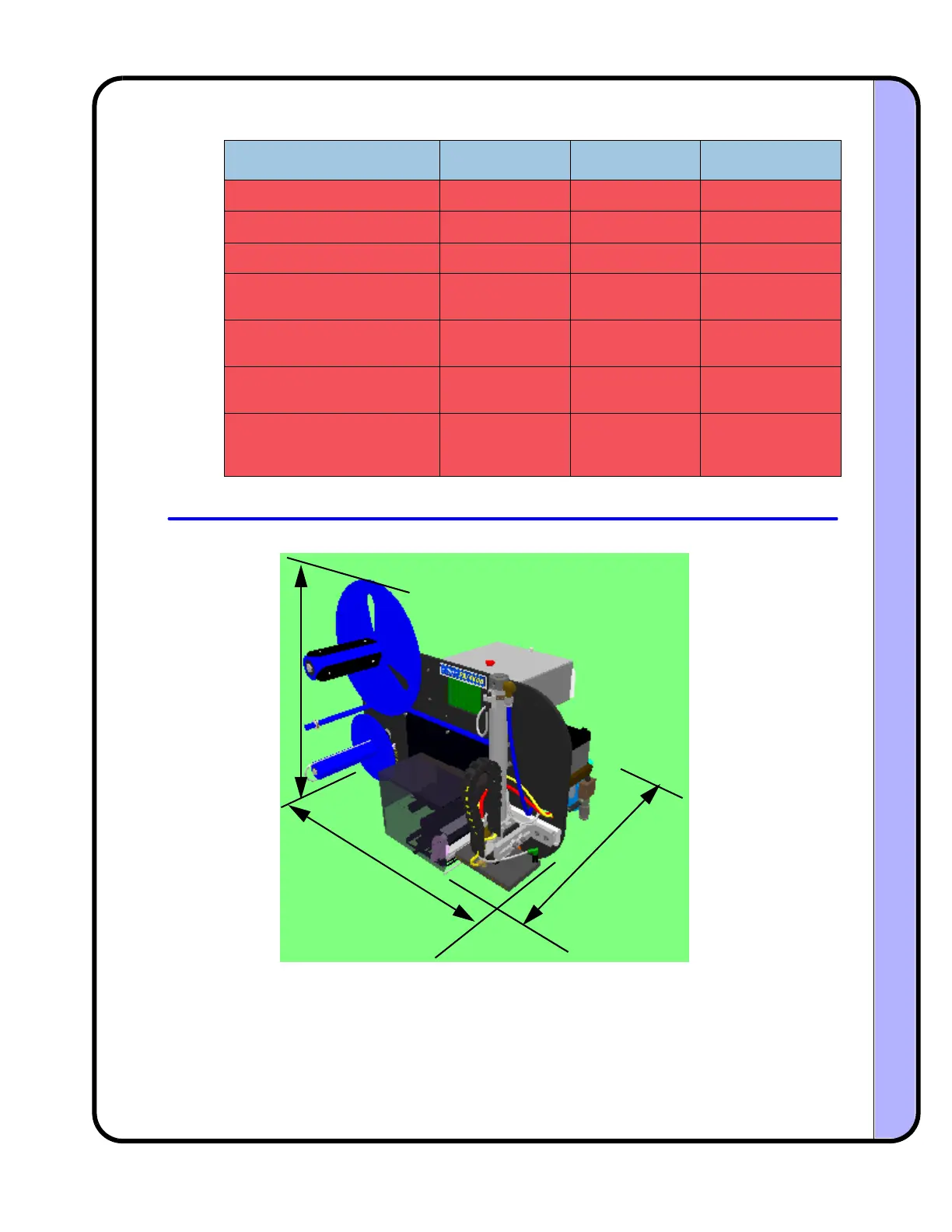
1.6 System Dimensions
3
1
i
n
.
23in.
2
5
i
n.
 Loading...