Do you have a question about the ITW Diagraph PA/6000 and is the answer not in the manual?
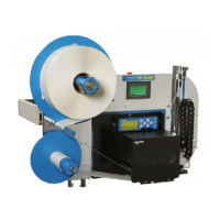
Describes the product's features and design, emphasizing modularity and ease of use.
Outlines critical safety warnings and compliance information for operating the device.
Explains formatting symbols used for notes, warnings, and goals in the manual.
Details the limited warranty provided for the PA/4600 and PA/6000 systems.
Lists general and electrical specifications of the equipment.
Details mechanical specifications for the tamp system, including air pressure and stroke.
Describes unwind, rewind, and tamp pad components of the system.
Details the stand assembly for the applicator, including its features and mobility.
Explains the pneumatic air manifold and tamp cylinder operations.
Describes the inlet air filtration and pressure regulation unit.
Details the main controller assembly (MCA III) and its capabilities.
Describes the SATO Lt 408 printer used in PA/4600 models.
Describes the rewind motor, its brushless DC design, and control.
Describes the auto-ranging power supply unit.
Details the infrared diffused light product sensor and its indicators.
Describes sensors for tamp pad presence and label low detection.
Describes the warning tower light assembly with colored lenses.
Explains the Festo pressure sensor and its features for monitoring air pressure.
Guide to choosing the best machine orientation for label application.
Instructions for connecting compressed air and AC power to the unit.
How to mount and adjust the product sensor for accurate detection.
Guide for initial system setup and configuration options.
Instructions for setting system parameters like Apply Mode and Baud Rate.
How to configure job-specific settings for label application.
Adjusting air pressure and quality via the inlet filter/regulator.
Loading label supply and ribbon for PA/4600 models.
Loading label supply and ribbon for PA/6000 models.
Guide to positioning the tamp cylinder module relative to the peel blade.
Adjusting pneumatic controls for tamp speed and air cushion.
Setting vacuum, air assist, and blow flow controls for optimal performance.
Performing test prints to optimize image quality and placement.
Creating and downloading label formats to the printer.
Making fine adjustments to optimize the tamp system's performance.
Performing final system optimizations for reliable operation.
Screens for initial system setup, sensor installation, and configuration.
Screens for configuring system-wide parameters like Apply Mode and Baud Rate.
Screens for configuring job-specific parameters like delays and durations.
Configuration of the auto-retract sensor function for optimized contact.
Settings to prevent feeding anomalies and ensure single label application.
Selection of triggers for printing, such as product sensor or tamp return.
Assigning a name to the current job for easier recognition.
Overview of diagnostic testing categories available on the unit.
Details on testing I/O, rewind motor, and printer functions.
Explains sensor and pneumatic diagnostic screens for troubleshooting.
Configuration of discrete input/output signals and their events.
Accessing various system information displays like Web Path and System status.
Managing the unit's power states, including entering standby mode.
Lists and explains various system warning messages and their meanings.
Lists and explains system error codes, their causes, and initial troubleshooting steps.
General problems and their solutions presented in a matrix format.
Problems and solutions specific to tamp cylinder operation and label transfer.
Solutions for labels buckling on the tamp pad due to vacuum or porting issues.
Solutions for labels feeding incorrectly due to pad position or cylinder home sensor.
Troubleshooting steps for air pressure errors, including minimum pressure checks.
Identifies and resolves issues related to air volume (CFM) and system performance.
Addresses common issues with label rolls, such as peeling or jamming.
Provides a schedule for routine maintenance tasks, categorized by frequency.
Instructions for performing system firmware upgrades using MTool2 software.
Lists parts recommended for replacement, organized by system component.
Illustrates assembly views with corresponding part numbers for reference.
Details the pin-out configuration for the product detector connection.
Details the pin-out configuration for the auxiliary port.
Details the pin-out configuration for the warning tower.
Details the pin-out configuration for serial communication ports.
Guide to setting up the Festo pressure sensor and its parameters.
How to monitor and check minimum and maximum pressure readings.
Procedure to reset the pressure sensor to its factory default settings.
| Print Technology | Thermal Transfer |
|---|---|
| Print Resolution | 203 dpi |
| Maximum Print Speed | 12 inches per second |
| Connectivity | Ethernet, USB |
| Power Requirements | 100-240 VAC, 50-60 Hz |