Diagraph - an ITW Company PA/4600 & PA/6000 User Manual
System Modules Page 7
System Modules
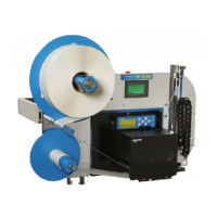
Stand P/N: 6160-329
2.2 Pneumatics SubSystem
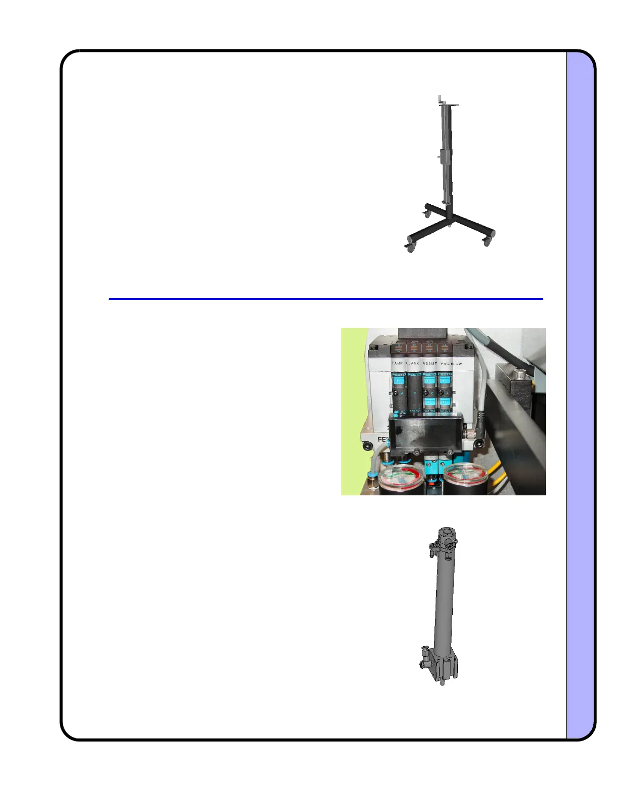
PAM (Pneumatic Air Manifold) P/N: 4600-701
Tamp Cylinder P/N: 4600-743 (10 inch), 4600-745 (20 inch)
ThestandholdstheyokeassemblyofthePA/
4600orPA/6000,andallowsthesystemtobe
orientated in a variety of positions to suit
applicationrequirements.Thestandemploys
a hand crank to set vertical position, and a
series of mounting pointsfor items such as:
warning tower, remote
user interface, and
inletfilter/regulator.Thestandcontainsthree
lockable casters that prevent rolling
movement, as well as rotational movement.
The column of the stand is designed to be
rotated, which can help installations where
the front leg of the t‐base interferes with
existingequipment.
The air manifold controls the operation of
the tamp cylinder and the delivery of the
label from the printer to the product. The
manifoldhastwopressureregulators,onefor
tamp pressure and the other controls both
vacuum and blow. Two flow controls limit
the volume of air going to the
air assist and
blow valves. There are two pressure gauges
that monitor the pressure set by the
regulators. A pressure sensor monitors the
incomingairlevelanddisplaysitonadigital
readoutandbargraph.Anerroristriggeredif
the incoming pressure drops below the set
pointvalue.
The tamp cylinder employs a dual‐rod
designtoachieve very highspeedextension
and retraction, without rotation. The tamp
cylinder extension and retraction speed is
controlled by means of the tamp pressure
setting on the air manifold and the flow
controlsonthe cylinderbody.Anadjustable
air cushion on
the top of the cylinder
dampensthereturnenergy. Amagneticreed
switch, attached to the top of the cylinder,
detectsthe immediate returnof the cylinder
toitshomeposition.
 Loading...