49
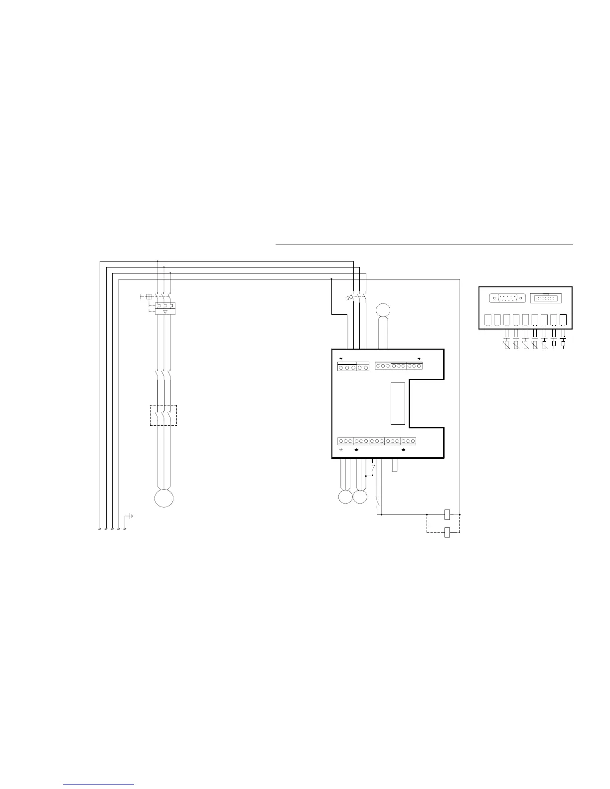
Circuit diagram Greenline D5-D11 3x400V
Model 11 has a built-in motor cutout in the pump,
*)
Givarkort interna kopplingar
Sensor Board internal couplings
*)
Kompressor
Plintkort
Terminal card
*)
**)
L2L1 L3 PEN
UVW
M
MB1
1
2
3
4
5
6
C1
1
2
3
4
5
6
F1
12
34
56
MB1
NLN
MB2
LL
P3
P2 COMP
NL1
N
ELB
LLN
T1 T2
SV1VXV P1
CLOSE
OPEN
OPEN
NLNL2 L3
M M
P3P2
43 44
MB1
CK1
A1 A2
VXV
M
Brown
Blue
Black
Softstarter, accessories
Motor cutout compressor
Motorskydd kompressor/
Contactor compressor
Kontaktor kompressor/
Circuit breaker heatpump
Automatsäkring värmepump/
MS:
F1:
CK1:
MB1:
Kompressor/ Compressor
Pressotat låg/ Low pressure switch
Köldbärare ut/ Heat transfer fluid (coll) out
Pressostat hög/ High pressure switch
Köldbärare in/ Heat transfer fluid (coll) in
Värmebärare in/ Heat transfer fluid in
Värmebärare ut/ Heat transfer fluid out
HP:
LP:
T9:
T11:
T10:
T8:
T6:
T11T8T6 T9 T10
MS
A1 A2
Compressor
Inkommande matning
Power supply
3x400V+N+PE
HP LPGT11VVP GT3 GT6 GT8 GT9 GT10
SERVICE J1
Mjukstart, tillbehör /
i modellerna 5-9 är en bygel monterad mellan L och MB2.
**) I modell 11 finns ett inbyggt motorskydd i pumpen,
models 5-9 have a clamp fitted between L and MB2.
MS
L1
T1
L2
T2
L3
T3