EasyManua.ls Logo

IXXAT CAN - User Manual

IXXAT CAN
7 pages
Print Icon
To Next Page IconTo Next Page
Loading...
Copyright IXXAT Automation GmbH
CAN Repeater - Manual, Version 3.6
1
CAN-Repeater
Manual
1. Description
The CAN-Repeater is used for electrical isolation of two segments of a CAN-
network, to increase the number of possible CAN nodes, for signal regeneration
and for setting up star or tree topologies. A special feature of the IXXAT
Repeater is an error detection mechanism with which a defective segment is
detected and shut down. The remaining network can thus continue
communicating without faults. The segment is reconnected to the network
automatically after the problem has been solved.
The automatic separation of a defective network segment is made after
reception of a permanent dominant level for more than 20 bit times. The
separated network will be reconnected after reception of a recessive bit.
2. LEDs
The status of the CAN Repeater and the CAN communication lines are indicated
by four LEDs mounted at the front of the housing.
Transmitting CAN 2 (green)
Status LEDs
Transmitting CAN 1 (green)
CAN 2 segment defect (red)
CAN 1 segment defect (red)
CAN 1
CAN 2
figure 2-1: Status LEDs of the CAN Repeater
Automation GmbH
Question and Answer IconNeed help?

Do you have a question about the IXXAT CAN and is the answer not in the manual?

Summary

CAN Repeater Description and Functionality

Repeater Functionality

Details the electrical isolation, node increase, signal regeneration, and topology support of the CAN-Repeater.

Error Detection and Recovery

Explains the automatic detection and shutdown of defective segments, and automatic reconnection after fault resolution.

CAN Repeater Status LEDs

LED Indicators

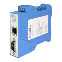
Describes the four LEDs indicating CAN Repeater status and communication line status, including transmit and defect states.

Power and CAN Connectors

Terminal Allocation

Details the pinning for power supply, second CAN line, and first CAN line screw connectors on the repeater housing.

Bus Termination Configuration

Termination Resistor Activation

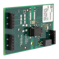
Explains how to activate or deactivate termination resistors (Rt=120 Ω) using soldering jumpers for CAN segments.

Configuration of Error Detection and Repeater Off-time

Error Detection Bit Time Configuration

Describes how soldering jumpers set the duration (20 bit times) for permanent dominant levels triggering segment separation.

Repeater Off-Time Adjustment

Explains enlarging repeater off-time via jumpers to handle high capacitance loads, with implications for round trip delay.

Technical Data and Available Options

Key Technical Specifications

Lists specifications including display, CAN interface, baudrate, delay, termination, power, size, temperature, and isolation.

Optional Repeater Configurations

Details options for reduced power consumption, faster bit rates, and CAN 2 as a low-speed interface/level converter.

Declaration of Conformity

Standards Compliance

States compliance with specified standards (DIN EN 55022, DIN EN 61000-6-2) and EC directives for the CAN-Repeater.

FCC Compliance Information

FCC Rules and Instructions

Details FCC Part 15 compliance conditions and instructions for Class A digital devices regarding interference.

IXXAT CAN Specifications

General IconGeneral
CategoryRepeater
FunctionRepeater
CAN Bus IsolationYes
Degree of protectionIP20
InterfaceCAN
ConnectorD-Sub 9

Related product manuals