L:\files\Manuals_For_Products\Engine_Manuals\Engine Maintenance Manual 22 & 33\JEM0002-5.docx
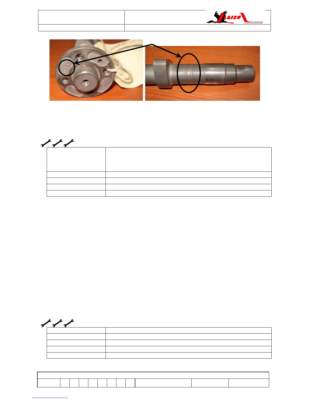
Figure 42 – Cam Identification Markings
Hydraulic Lifters can be ‘bled’ back while installed by using a suitable tool to push
rocker/pushrod assembly back to enable a small gap on rocker to valve tip. Total bleed-back is
less than 2 mm. More details are given in the engine overhaul manual.
9.20.1 Hydraulic Lifter Removal
If required, hydraulic lifters can be removed for inspection using the following method:
a. Remove the air ducts and rocker covers from the engine.
b. Ensure the piston of the cylinder being worked on is at the bottom of its stroke.
c. Use a valve compression tool (Figure 16) to open both valves slightly. This takes the
spring load off the rockers and allows their removal.
d. Remove the central screw holding the rocker shaft in place.
e. Remove the rocker pivot shaft, rockers and pushrods from the cylinder head to be
inspected. Note that for a 3300 engine it is easier to remove the entire head if one of the
middle cylinders needs to be worked on.
f. Remove the pushrod tube retaining circlips from the cylinder head and slide the pushrod
tubes out through the head.
g. Remove the hydraulic lifter adaptors from the crankcase
h. Remove the lifters.
Whenever lifters are removed the working face of the cam and the lifter should be inspected for
damage. If damage is found, contact Jabiru Aircraft P/L or our local representative for further
guidance.
Note that this is not a part of normal scheduled maintenance but may be necessary for
troubleshooting.
9.20.2 Valve Rockers