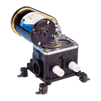
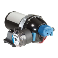
INSTALLATION
STEP 1
Determine the distance from the power source to the pump
and then double the measurement. Wire gauge installation is
determined on the entire r
un length, to the pump and back.
STEP 2
Connect to power supply lead (red)(+) to the positive (+)
terminal on the battery or thr
ough a properly installed fuse /
circuit breaker panel. Then run the length of wir
e to the pump,
connecting the red wire through a switch appropriately rated
to the pump’s current requirements.
STEP 3
Route the wire so as not to create hazards in operation of the
engine, movement of steering components or human traf
fic.
WIRING (Fig. 3)
STEP I
Remove shipping plugs from pump ports. There may be slight
amount of water that drains out of the pump as all pumps are
tested at the factory before shipment.
STEP 2
A direction arr
ow can be found on the pump head to indicate
dir
ection of flow. Connect the appropriate sized hose to one of
the supplied fittings and then connect the hose to the water
supply tank outlet. T
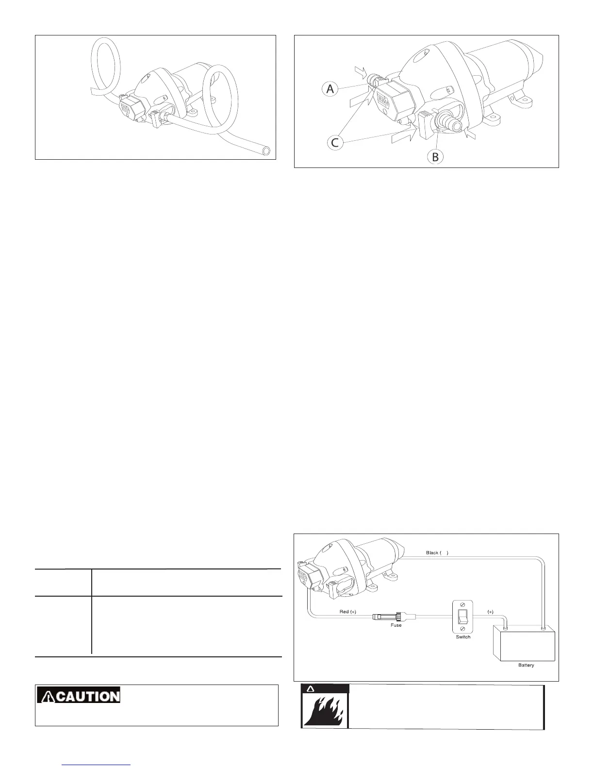
o reduce vibration use 1/2” (13 mm)
braided or reinforced flexible hose on the inlet and outlet of the
pump as shown on Fig.1. Use hose clamps on the slip-on barb
connectors.
FIG. 2
FIG. 3
WIRE SIZE
TABLE
Pump
Voltage
0 - 20 ft
(0 - 6 m)
20 - 35 ft
(6 - 9 m)
35 - 55 ft
(9 - 12 m)
12 VDC #14 AWG
(2.5 mm
2
)
#12 AWG
(4 mm
2
)
#10 AWG
(6 mm
2
)
24 VDC #16 AWG
(1.5 mm
2
)
#14 AWG
(2.5 mm
2
)
#12 AWG
(4 mm
2
)
Total Wire Length
- feet (meters)
STEP 4
Connect the red lead to the red lead on the pump housing located
pressure switch.
STEP 5
Connect the black lead from the pump to the gr
ound or negative
power side (-) of the vessel.
STEP 6
Turn the system off when not in use for extended periods of time or
when the water supply tank is empty.
STEP 7
After installation, check voltage at the pump motor. Voltage should
be checked when pump is operating. Full voltage must be available
at the pump motor at all times for proper pump operation and pump
motor life.
Motor case could get hot during
extended operation. Prolonged contact with skin may
cause a burn.
WARNING
!
Fire hazard. Wiring must comply with
applicable electrical standards and include
a properly sized fuse or circuit breaker.
.
Improper wiring can cause a fire resulting
in injury or death.
STEP 3
Slide rubber mounts fully into 4 mounting tracks.
STEP 4
Mount pump horizontally in an accessible location or vertically with
pumphead down. Support weight of the pump and attach
pumphead mounts first then motor mounts second.
STEP 5 (Fig. 2)
Install inlet A and dischar
ge B port connectors. Firmly push slide
clips C forward to lock port connectors in place.
STEP 6 (Fig. 4)
Install a Pumpgar
d
TM
strainer in an accessible location (for
inspection and cleaning) between the tank and pump inlet in order to
protect valves from debris.
IF YOU ARE NOT FAMILIAR WITH APPLICABLE ELECTRICAL STANDARDS, HAVE THE UNIT INSTALLED BY A QUALIFIED
ELECTRICIAN.
Suggested wiring information is given as a reference. For proper information, please refer
ence USCG regulations for marine applications
and wiring gauges, connectors and fuse protection.
FIG. 1
PumpAgents.com - buy pumps and parts online



 To Next Page