J33
J36 J46
J41 J47
J49
J38
J53
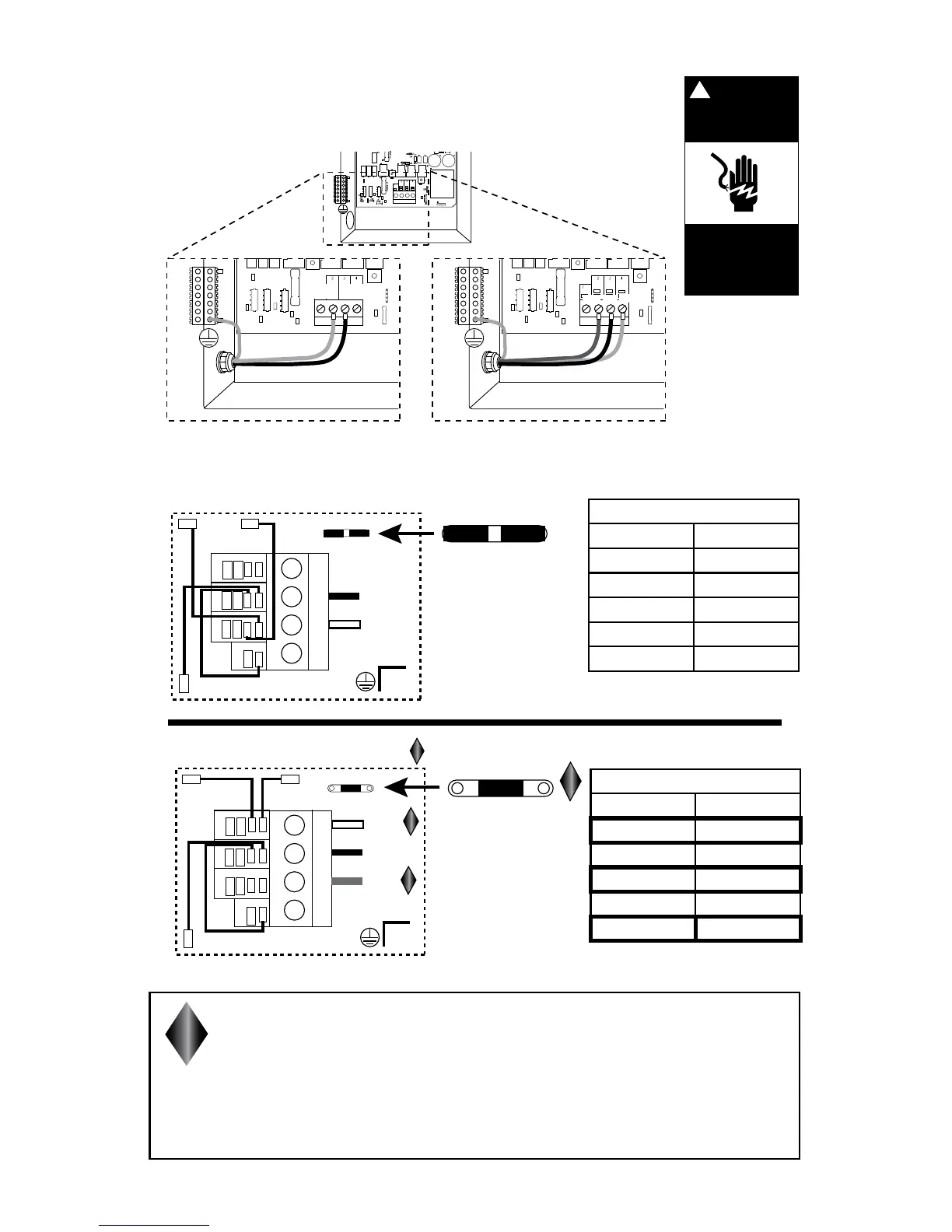
TB3
120 VAC 3-Wire connection 60 Hz
240 VAC 4-Wire connection 60 Hz
A
B
C
D
J37
J44
J73
J72
J74
J35
J33
J36 J46
J41 J47
J49
J38
J53
Wht
Black
Green
TB3
OR
TB1
A
B
C
D
J37
J44
J73
J72
J74
J35
J33
J36 J46
J41 J47
J49
J22
240V
120V120V
J38
J53
Wht
Blk
Red
J22
240V
120V120V
TB1
TB1
GRN
BLK
WHT
120V 3-WIRE CONNECTION
240V 4-WIRE CONNECTION
J51
J33
1
2
3
4
J41
J47
J53
J38
J46
J36
J37
J59
GRN
WHT
BLK
RED
J51
J37
J59
A
B
C
D
240V
120V 120V
J22
240V
120V 120V
J22
J33
1
2
3
4
J41
J47
J53
J38
J46
J36
A
B
C
D
J22
120V 120V
240V
J22
120V 120V
240V
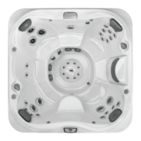
Jumper Wires
FROM TO
J37 J36
J51 J46
J59 J41
J33 J47
J22 2 jumpers
Jumper Wires
FROM TO
J37 J38
J51 J46
J59 J53
J33 J47
J22 1 jumper
CAUTION: (FOR A 4-WIRE 240 VAC HEATER OPERA-
TION.) The jumper at location J22 must be changed from
a 120V to a 240V conguration. Make sure to connect the
wires as shown at TB1, for a 240V connection, before apply-
ing power. Jumper wires MUST be changed. Failure to follow
these steps will result in damage to the circuit board and/or
related components and void the manufactures warranty.
DANGER
Turn power off
before servicing. This
task should only be
performed by a quali-
fied technician.
!
RISK OF SHOCK OR
ELECTROCUTION!