ENGLISH
13
Jacuzzi Whirlpool Bath EL21000B 10/06
Framing and Support
The drain/overfl ow of the bath extends below the bottom of the bath. Note that this requires a cutout in the fl oor.
The fl oor structure beneath the bath must be able to support a total weight of bath, water, and bather. Refer to the
table under total weight for your model. The unit must be supported from the bottom of the bath and not from the bath rim
or nailing fl ange. If the subfl oor is level and a continuous surface, no other preparation is necessary. You can proceed to install
the bath. If the subfl oor is not level, you MUST level the entire surface prior to installing the bath. The use of materials that shim
or provide a level installation are allowed provided the method used will insure a level bath that is supported from the bottom.
Materials that may be used are a fl oor leveling compound, mortar, plaster or minimal expansion structural foam; however the
bath must remain level in order for it to drain properly and all foam feet must make full contact with the leveling material. Both
sides of a joint or splice of subfl oor should be level to each other.
NOTE: Drop-In Bath units are equipped with metal anchor straps. These straps can be used to secure the unit to the
fl oor or sub-fl oor to reduce movement after installation. If mortar or similar anchoring material is used, these straps
are not necessary.
WARNING: ALL foam feet must contact the fl oor. Anchoring straps and/or other anchoring materials will not properly
anchor unit if ALL foam feet are NOT in contact with a level fl oor. Operating a unit improperly installed may cause ir-
reparable damage to the unit.
The rim of the bath is not designed to support weight. If fi nish material is to overlap or contact the bath, the added weight
must be fully self-supporting.
Install optional trim parts when all installation has been completed.
The protective fi lm liner inside the bath is used to help prevent damage to the fi nish during installation. Before instal-
lation, remove liner to inspect for any defects, reapply and do not remove until fi nal cleanup.
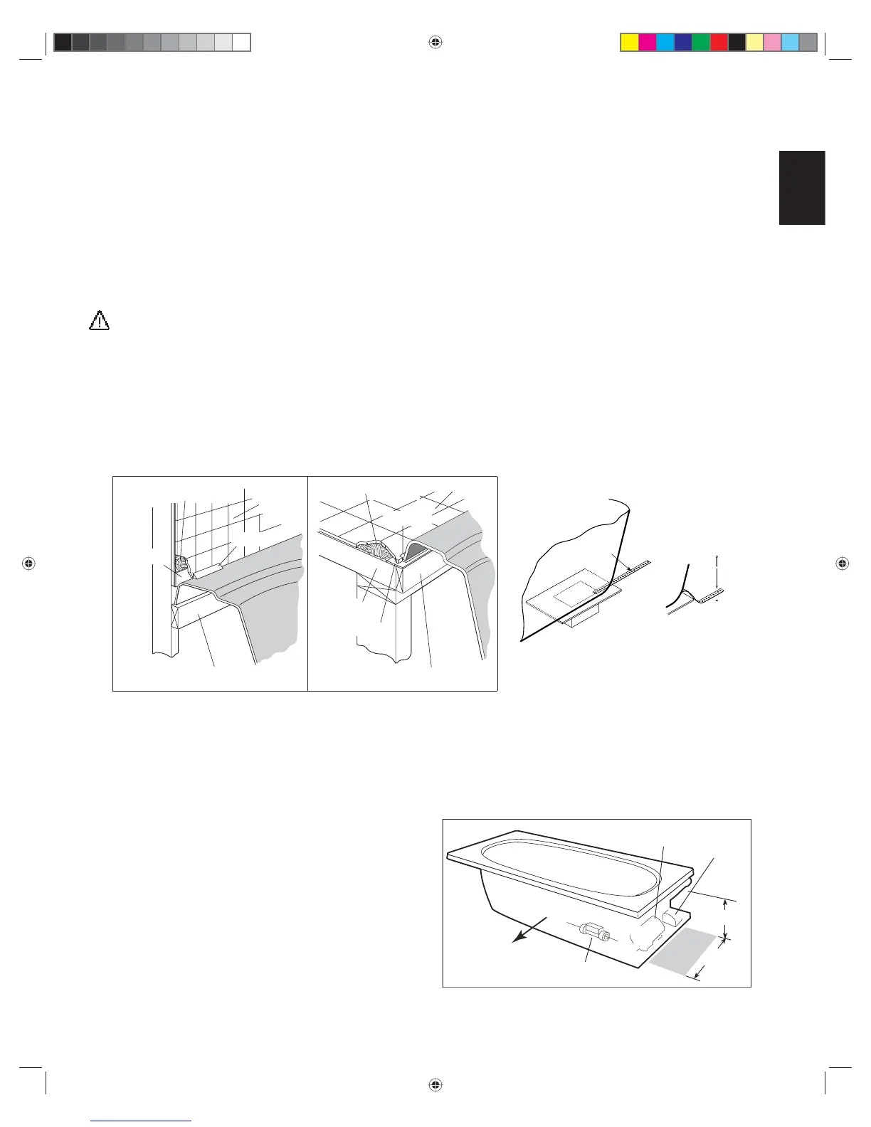
FLUSH TO WALL
SEMI-SUNKEN
TILE
1" X 4" (NOT FOR SUPPORT)
MORTAR OR ADHESIVE
FLASHING
SEALANT
SUB-FLOOR
FLASHING
SEALANT
MORTAR OR ADHESIVE
TILE
TYPICAL INSTALLATIONS
1" X 4" (NOT FOR SUPPORT)
INSTALLATION
NAIL OR SCREW
THROUGH
ANCHOR STRAP
INTO FLOOR
FLOOR
ANCHOR
STRAP
Service Access
For partially or fully sunken installations, allow for access to
service connections. It is the installer's responsibility to pro-
vide suffi cient service access. The recommended minimum
dimensions allowable for service to the bath are shown in the
"Service Access" illustration below.
Provide adequate ventilation for cooling and to supply suf-
fi cient air for the blower. Also provide adequate area around
unit for air circulation for cooling the motor and to supply suf-
fi cient air to the jets.
Do not insulate this area or around blower or motor.
PUMP/MOTOR
24"
PUMP/MOTOR & BLOWER SERVICE ACCESS - REQUIRED
12"
BLOWER
FRONT
HEATER