31
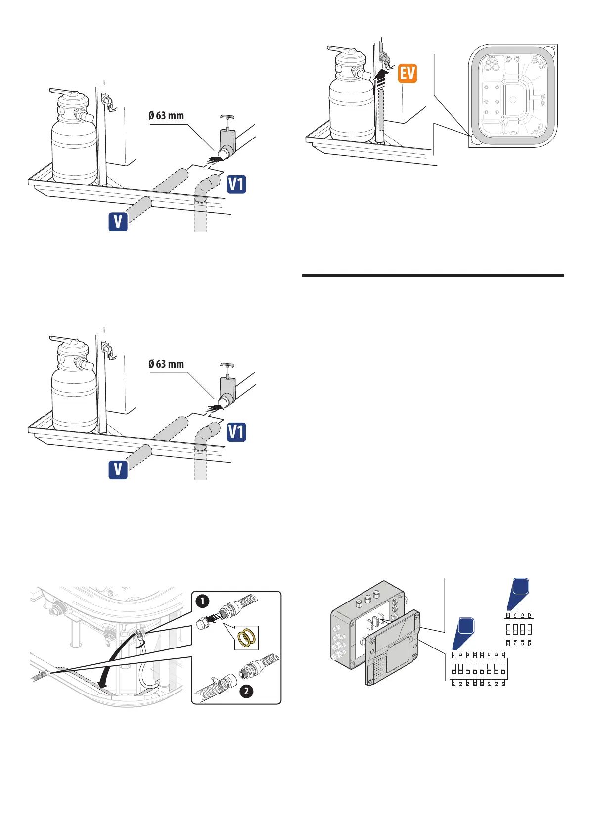
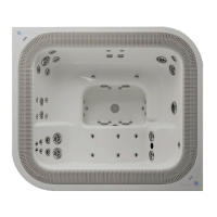
Refer to the pre-installation instructions for information on
connecting the drain. Also connect the overow on the balance
tanks (position W or W1).
n
CAUTION: the overow drain on the compensation
tanks must always be left open.
m
CAUTION: the two drain lines (hot tub drain, parts V/
V1 and overow drain, parts W/W1) can be connect-
ed together but NOT BEFORE the respective sluice
valves, otherwise the entire system may not function.
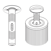
Note on connecting the balance tank drain: the factory in-
stalled pipe is tted with a connector with gaskets, which the drain-
age system in the building can be connected to. Alternatively, the
balance tank can be connected directly to the drain (remove the
factory installed pipe) and the connector supplied (or a valve) can
be used to drain the water as necessary.
Connect the solenoid valve to the water mains.
■ Model can be used witH Jacuzzi® Heat puMp (eco-Heat/
c
oolpower): connect the tub to the heat pump (see the rele-
vant manual).
Install the locking system of the cover (0 4).
Electric connections and safety
The installer is responsible for choosing wires with characteristics
and nominal section that are suitable for the specic current input
of the hot tub (see pre-installation instructions).
The cable path, choice of materials and most suitable installa-
tion solutions are left to the professional knowledge and experience
of the installer; it is his responsibility to guarantee and certify the
installation.
Connect to the terminal block as indicated in the following
wiring diagrams (0 5).
n
IMPORTANT: for Countries where 220-240V voltage is
supplied by a two-phase system (L+L), the connection
has to be made on terminals L1 and N anyway.
NOTE: If the electrical system that powers the SPA consists of
two (or three) phases (+ neutral, 380-415 V 2-3N ~) before con-
necting, remove the jumper/s located near the terminal board.
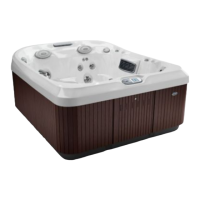
Check the arrangement of the switches ("dip-switch"), based
on the spa model and the chosen settings.
b1
b2
1 2 3 4 5 6 7 8
ON
1 2 3 4
ON
SWITCHING BENCH "b1"
dip switch 1 Electric consumption limitation (OFF=16A; ON=32A).
dip switch 2 Pump 1 (check that it is in the OFF position).
dip switch 3 Pump 2 (check that it is in the ON position).
dip switch 4 Blower (OFF = present; ON = absent).
dip switch 5 Filtration pump (OFF = present; ON = absent).