Page 31
ENGLISH
Jandy
®
, JXi
™
Gas-Fired Pool & Spa Heater
|
Installation & Operation Manual
NOTE: OnlyanAquaLink®RSSystemwithrmwarerevision“N”,orhigher,willsupporttheheaterinterface.RefertoTable 6 along with Figure
18 and Figure 19todeterminetheREVofyoursystem’srmware.Ifitis“N”orhigher,continuewiththeseprocedures.IfitisMMMorlower,
follow the procedures in Section 7.2 for connecting to a remote TSTAT.
NOTE: OnlyaPDASystemwithrmwarerevision4.1,orhigher,willsupporttheheaterinterface.
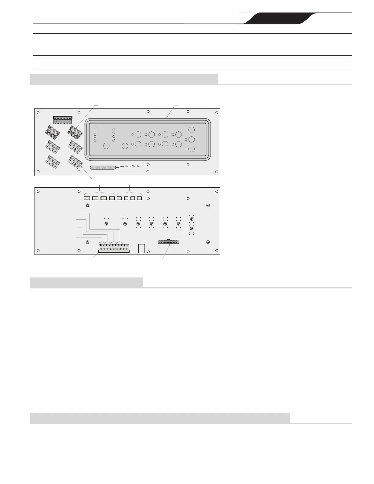
8.3.2 PCB Identication for AquaLink
®
Innity™ Connections
Connect via RS485 connection. See Section 7.3.3
for details.
RS 485 Connector Socket (6X)
Blue Board Connection Terminal
(J21)
Relays
(J13-J16)
JVAs
(J17-J20)
Green Terminal Bar
(J11)
Air Temperature Sensor
Water Temperature Sensor
for Dual Body Applications
RS 485 4 pin connector (2X)
SPARE
AUX3AUX2AUX1AUX0
F-PUMP
JVA3/
CLEANER
JVA4/
SOLAR
JVA1/
INTAKE
BLU
BRN
WHT
GRN
BLK
RED
SPA SIDE SWITCH
AIR WATER SOLAR LVH
RED
GRN
YEL
BLK
RED
GRN
YEL
BLK
RED
GRN
YEL
BLK
RED
GRN
YEL
BLK
RED
GRN
YEL
BLK
RED
GRN
YEL
BLK
JVA2/
RETURN
UWater Temperature Sensor
Solar Temperature Sensor
Figure 20. AquaLink Innity PCB
8.3.3 RS485 Connection Procedure
• Turn off the power to both the heater and the controller.
• Open the power center enclosure and remove the low
voltage dead front.
• Use 22 gauge 4-conductor wire to run between the
heater and the control system and match the wire
color order. See Figure 17.
• The wires coming from the heater can be “doubled
up” on the red RS485 terminal bar with the four
wires from the indoor controller.
• Check all wiring, then apply power to both the heater
and the control system. Verify operation in either
Service or Auto mode. Refer to your Control System
manual for operating instructions.
When the heater is connected to an external controller,
all functionality of the heater control panel is disabled,
therefore heater functions can be controlled only from
the controller. Control can be restored to the local heater
control panel by either disconnecting the red RS485
terminal or by entering the service setup mode selecting
REMOTE then STANDALONE. Control can be sent
back to the external controller by re-entering the service
setup mode and selecting JANDY RS485, unplugging
and replugging the RS485, or by cycling power to the
heater with the RS485 connected.
Do not connect more than two (2) wires to any of the
terminals in the Control System when connecting
peripheral devices. If connecting the heater to the control
system creates this situation, then a Multiplex PCB Kit,
which includes the Multiplex Board (part # 6584) must
be used. Call Jandy Technical Support at 800.822.7933
with any questions.
8.3.4 To Stop the Heater and Prevent Firing After Connecting to an External Controller
• Turn power to the heater ON. The heater display
shows: JANDY REMOTE ONLINE PUSH MENU
TO DISABLE.
• After pressing menu, the display will show
JANDY REMOTE OFFLINE PUSH MENU TO
ENABLE.
 Loading...