Janfire NH Burner Service Installation Manual 4.16.09 - Technical specifications are subject to change without prior
notice.
34(38)
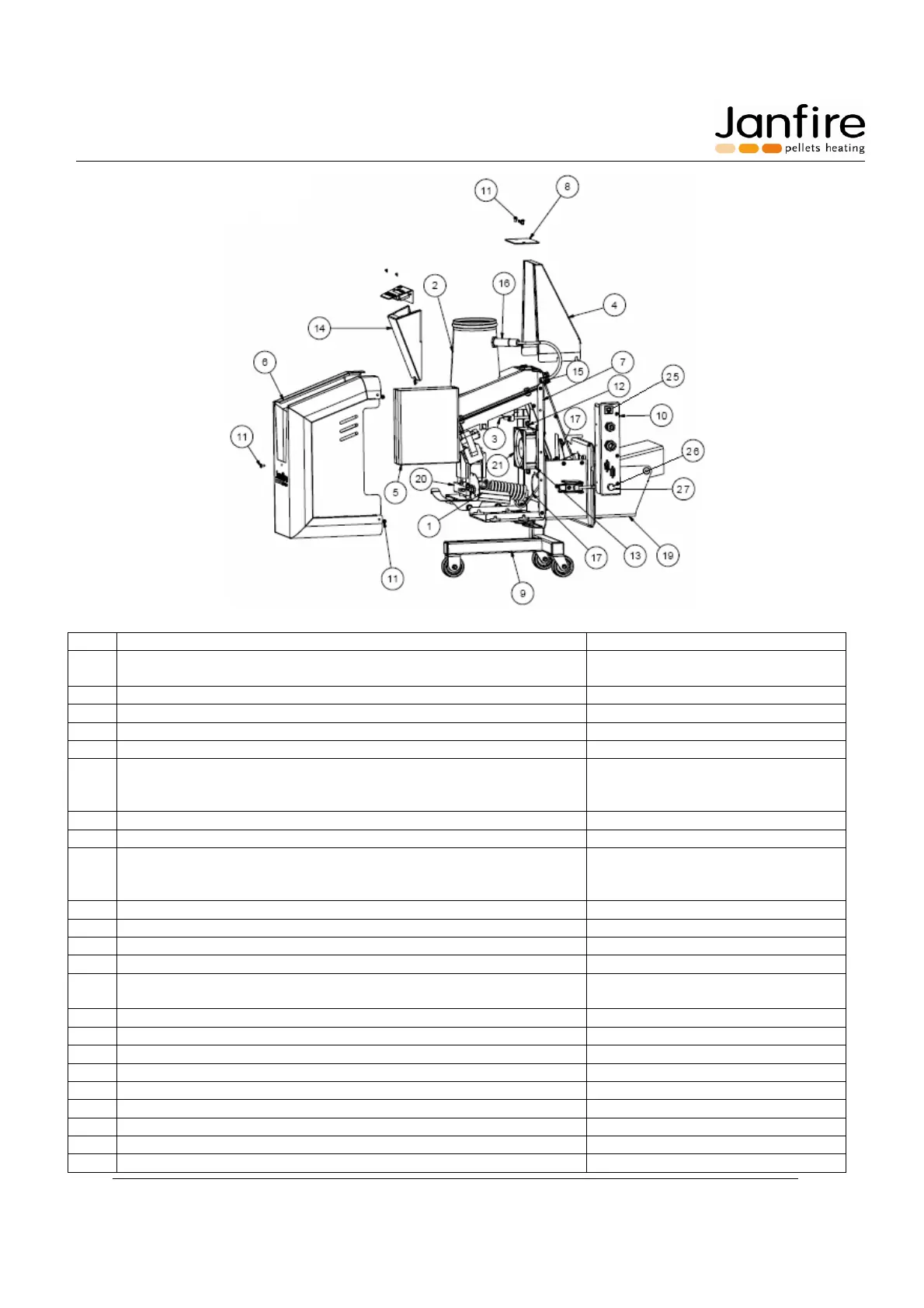
Figure 12. Parts breakdown of NH Burner
Description Part No.
1 Heating element 11802007
11842004
2 Internal Hopper See Fig. 13
3 Microswitch 71842003
4 Drop shaft shroud 11801333
5 Control box 71843009
6 Cover 11802011
11802019
11802013
7 Frame 11801020
8 Drop shaft inspection cover 11801025
9 Trolley 11801017
11815001
11815002
10 Connection plate 71842042
11 Allen screws M4x10 80463005
12 Flange screw M6x12 80661003
13 Allen screw M3x12 80363003
14 LCD assembly 11801021
71843018
15 Grommet 11815009
16 Capacity sensor 70046003
17 PT100 Dropshaft sensor 71842047
19 Burning cup frame 11802014
20 Element Backer 11842004
21 Fan 11835002
25 10 Amp circuit breaker 71842045
26 Fuse Holder 71842046
27 Fuses (15 Amp fast blow) 71842043