-3-
Pay attention to the correct wiring.
Improper connection may damage the device.
A
A1: AMP_POW (Amplifier control)
A2: GND (RCA_FL/RCA_FR)
A3: AUXIN_R (Right channel input)
A4: RCA_FL (Front left audio output)
A5: AUXIN_L (Left channel input)
A6: RCA_FR (Front right audio output)
A7: NC (Not used)
A8: GND (AUX IN_L/AUXIN_R)
A9: NC (Not used)
A10: GND (CVBS_IN2)
A11: NC (Not used)
A12: GND ground (CVBS_IN1/CVBS_OUT)
A13: NC (Not used)
A14: NC (Not used)
A15: NC (Not used)
A16: SUB subwoofer output
A17: CVBS_IN2 video input 2
A18: CVBS_IN1 video input 1
A19: MIC-microphone -
A20: MIC+ microphone +
C
C1: GND (AUX IN_L/AUXIN_R)
C2: POW_12V
C3: AUX2_L
C4: AUX2_R
C5: KEY_RST
C6: IPOD_DET
C7: CAN_TXD(CANBUS)
C8: CAN_TXD(CANBUS)
F
F1: TXD_TPMS OBD
F2: NC (Not used)
F3: RXD_TPMS OBD
F4: GND
F5: POW_5V(TPMS)
F6: CAM_CVBS(Reverse image)
F7: CAM_12V(Reverse image)
F8: CVBS_GND(Reverse image)
F9: PARK_IN(Hand brake detection)
F10: GND
D
D1: USB_5V
D2: USB_DP0 USB0
D3: GND USB
D4: USB_DN0 USB0
E
E1: USB_5V
E2: USB_DP1 USB1
E3: GND USB
E4: USB_DN1 USB1
E5: USB_DN2 USB2
E6: USB_DP2 USB2
G: Main Power Cable
1
2
3
4
5
6
7
8
9
10
11
12
13
14
15
16
G
G1: GND
G2: B+ 12V
G3: ACC +12V
G4: ILL (Car headlights)
G5: Reverse Detection
G6: KEY 2
G7: KEY 1
G8: Automatic Antenna Power Supply
G9: FR- (Speaker Front Right)
G10: RL- (Speaker Rear Left)
G11: FR+ (Speaker Front Right)
G12: RL+ (Speaker Rear Left)
G13: FL+ (Speaker Front Left)
G14: RR+ (Speaker Rear Right)
G15: FL+ (Speaker Front Left)
G16: RR- (Speaker Rear Right)
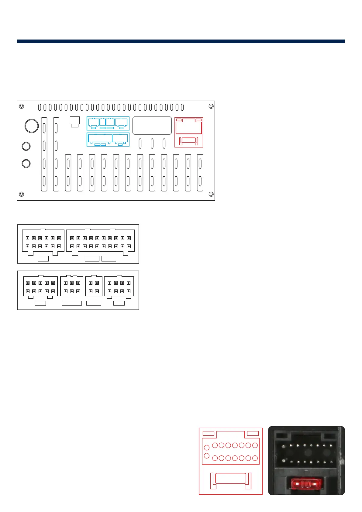
1. Installation Notes
1.1 Pinout diagram of the device connector
1.2 Wiring Diagram
A B
C
D E F
G
H
I
J
ANT
GPS
4G+
POWER
K
A:Audio / Video Connector
B:Redundant expansion (not
allowed third-party connectors)
C:CANBUS Connector
D:USB(4 PIN)
E:USB(6 PIN)
F:Reverse Video Out
G:Main Power Cable
H:Radio
I: GPS
J: 4G Antenna
K: Optical audio output
1
2
3
4
5
6
7
8
1
2
3
4
1
2
3
4
5
6
1
2
3
4
5
6
7
8
9
10
C
DEF
A
1
2
3
4
5
6
7
8
9
10
11
12
13
14
15
16
17
18
19
20
1
2
3
4
5
6
7
8
9
10
11
12
B
(Not Used)