7
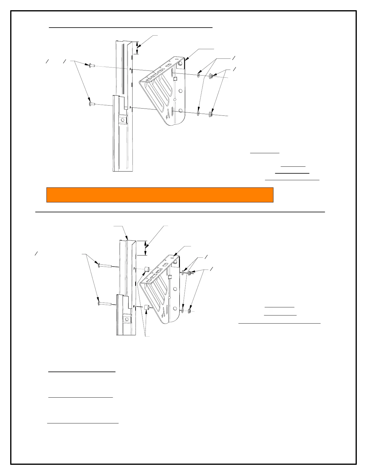
FIGURE 6:
COMMERCIAL
BRACKETS TO GUIDE
FIGURE 7:
DRIVE END
(RH SHOWN \ LH OPPOSITE)
►Attach commercial brackets to guides, locating top surface of
b
racket 2" below top of guide. Use (2) 1/4" - 20 x 5/8"
c
arriage bolts, (2) 1/4" - 20 serrated flange hex nuts
an
d (2) 1/4" flat washers per bracket for tensioner en
d
and the non-tensioner (drive) end. For push-u
p
o
peration
. See Figures 6
►REDUCED HAND CHAIN DRIVE: Install drive bracket 2" from top of guide to top of bracket with two (2) each 1/4" - 20 x 1-3/4"
ca
rriage bolts 1/4" - 20 serrated flange hex nuts and 1/4" flat washers.
*Insert one (1) each 5/8" O.D. x 1/2" long spacer tube
be
tween guide and bracket at each bolt location.
►ELECTRIC OPERATOR DRIVE: Install drive bracket 2" from top of guide to top of bracket with two (2) each 1/4" - 20 x 2-1/2"
ca
rriage bolts, 1/4" - 20 serrate flange hex nuts and 1/4" flat washers.
*Insert two (2) each 1- 1/2" O.D. x 3/4" long spacer tubes
be
tween guide and bracket at each bolt location.
►PANTHEON MOTOR OPERATION: Install drive bracket 2" from top of guide to top of bracket. Position bracket 1-1/4" from
out
side of guide to inside of the bracket.
*No spacers are required for this application.
1
4" - 20 CARRIAGE BOLTS
TOP OF GUIDE
COMMERCIAL BRACKET
1
4" - 20 SERRATED HEX NUT
1
4" FLAT WASHER
*SPACER TUBE (SEE INSTRUCTION BELOW FOR OPTONAL DRIVES)
POSITION BRACKET 2"
FROM TOP OF GUIDE
TO TOP OF BRACKET
STEP 3: COMMERCIAL BRACKETS TO GUIDES
1
4" - 20 x
5
8"
CARRIAGE BOLTS
POSITION BRACKET 2"
FROM TOP OF GUIDE
TO TOP OF BRACKET
COMMERCIAL BRACKET
1
4" FLAT WASHER
1
4" - 20 SERRATED HEX NUT
NOTE: DOOR DRIVE OPERATION MAY BE INSTALLED ON EITHER END OF DOOR ASSEMBLY.