11
JB INDUSTRIES • ELIMINATOR OPERATING MANUAL • 800.323.0811 • SALES@JBIND.COM • JBIND.COM
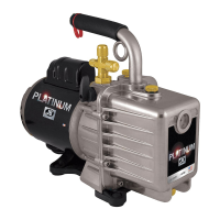
Removing Cartridge
Remove four cartridge screws with 7/16" or 3/8"
wrench (Figure 26)
. Discard old gasket seal and
two o-rings along with cartridge and bolts.
Replacing Shaft Seal
and O-rings
Step 1: Insert screwdriver blade under shaft seal
and pry the seal from the housing being
careful not to damage the walls or face of
the trap (Figure 27)
.
Step 2: With clean rag, remove all oil and residue
from inside hole and front and back of trap.
Step 3: Lay trap on flat surface with handle
toward you. Press new shaft seal with
flat side down into opening by hand. To
seat, tap seal with 11/16" socket. Seal is
properly seated 1/8" down from top edge
(Figure 28)
. Apply petroleum jelly or
grease to inside edges of seal.
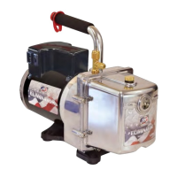
Step 4: Insert intake and gas ballast o-rings in
trap (Figure 29). Gasket replaced after
cartridge is installed.
Replacing Pump Cartridge
Read section carefully before attempting
replacement.
Step 1: Keep trap flat on bench. Remove holding
nuts from cartridge, keeping all
parts in alignment. (Four nuts can
be discarded.) Cartridge is held with
shaft down and flutter valves facing intake
fitting. Center shaft with seal opening
(Figure 30). Align with threaded holes and
place in position. Hand tighten four bolts.
Cross tighten with 7/16" wrench.
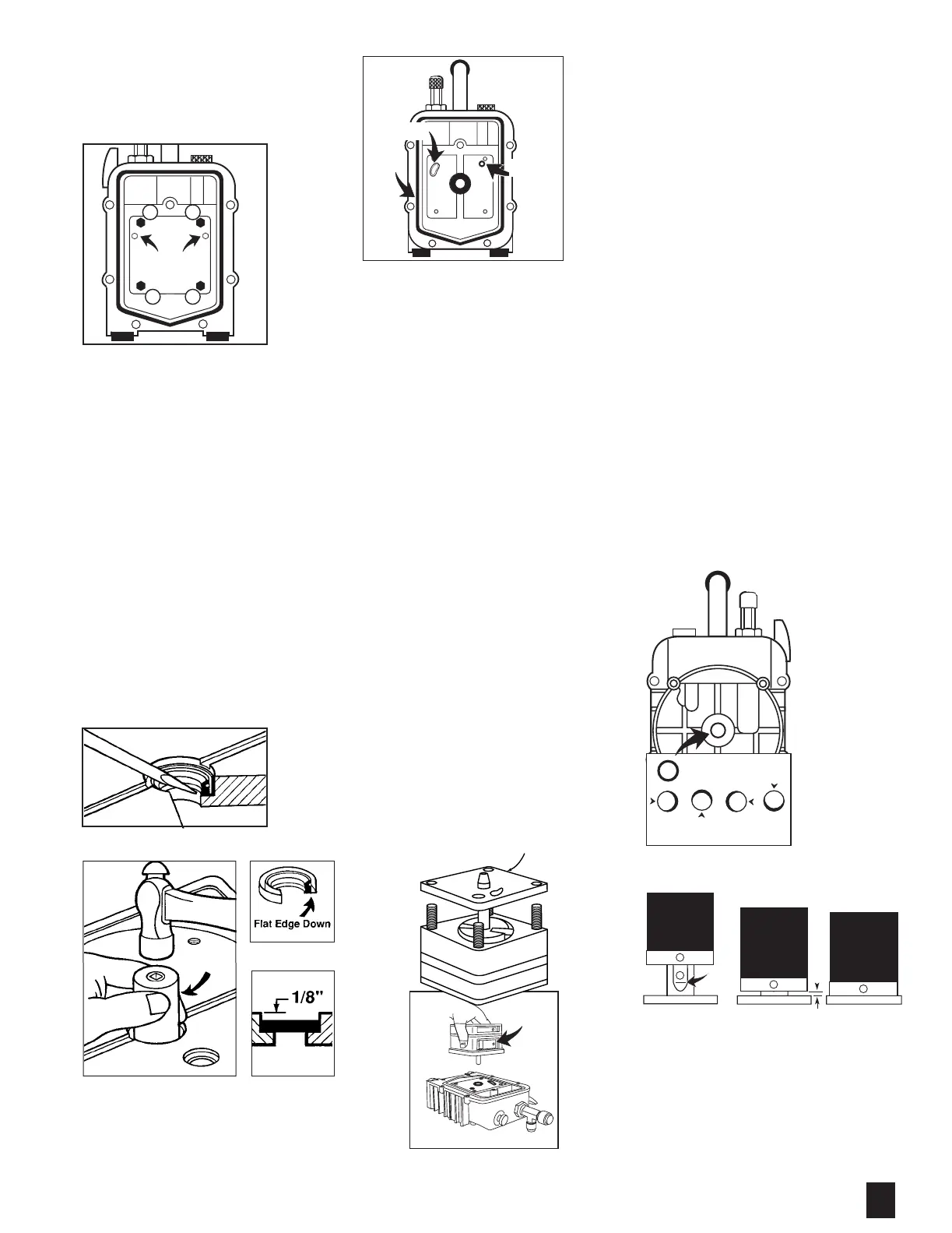
Step 2: Check alignment by rotating shaft with
coupler. If shaft moves freely continue
assembly. If shaft binds, loosen bolts
and turn shaft until shaft rotates freely.
Retighten bolts. Shaft should be concentric
with shaft hole when viewed from backside
(Figure 31)
.
Step 3: Replace gasket (Figure 26) and reinstall
oil cover to trap (Figure 25)
.
Step 4: Remove set screws on coupler. Coat set
screw threads with thread sealant. Reinstall
coupling to pump cartridge with set screw
facing flat side of shaft. Tighten screw so
coupler slides on shaft but stops at bottom
of flat. Tighten until screw head is flush with
coupler. Coupler should be approximately
1/8" off trap surface (Figure 32).
Replacing Motor
Step 1: With pump standing on oil cover, rotate
coupling so set screws are facing trap
assembly opening. Reinstall motor while
aligning flat side of motor shaft with set
screw. IMPORTANT: Assemble in
This Order:
a. Tighten four motor screws.
b. Tightened coupler set screw on
motor shaft.
Step 2: Reinstall foot mounting bracket and
rubber feet.
Before Operating
Step 1: Be sure pump switch is in OFF position and
plug in.
Step 2: Open oil drain and intake cap. While pump
is running, immediately place two to three
ounces of fresh oil into intake and run
pump for three to four seconds. Repeat
procedure at least two times. Allow oil to
drain out.
Step 3: Close oil drain and replace intake cap.
Step 4: Fill with new JB BLACK GOLD Vacuum
Pump Oil to top edge of oil level line. For
those pumps without line, the correct level
is 1/8” below top of sight glass. Replace oil
fill plug.
Step 5: Run vacuum test.
Do not disturb
hex setting
screws
1 2
4 3
Figure 26
Figure 27
Figure 29
Cover
Seal
Intake
O-Ring
Gas Ballast
O-Ring
Figure 28
11/16"
socket
Figure 30
If new intake plate on cartridge
differs from the old intake plate,
use the old intake plate.
Intake
Valve
Figure 32
(Coupler styles may vary from illustration)
Bottom of Flat Correct Incorrect
Figure 31
Shaft Aligned
Correctly
Shaft Touching Edge
Of Trap Hole
 Loading...