M
mark63Jul 29, 2025
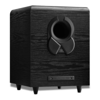
What to do if my JBL 1500 has low or no bass output?
- AamandahillJul 29, 2025
If your JBL Subwoofer has low or no bass output, verify that the connections to the left and right 'Speaker Inputs' have the correct polarity (+ and –). Also, ensure the subwoofer is plugged into an active electrical outlet and that the Power Switch is on. If you are using Dolby Digital or DTS modes, check that your receiver/processor is configured to enable the subwoofer and LFE output. Finally, adjust the Subwoofer Level Control.