+16
+10
0
-10
-20
-30
-40
-50
-60
-70
all
-w
-100
lmJ
t24
+20
+10
c
t6dBu 0
-10
-20
-3
-40
-XI
-60
-70
106d8@lm
L
62dBQ2Om~Ims
Setiprtdan@ierso,Ihat
t6dBuinpmducesoutputd
t6av(&3mlts)inb6dnw
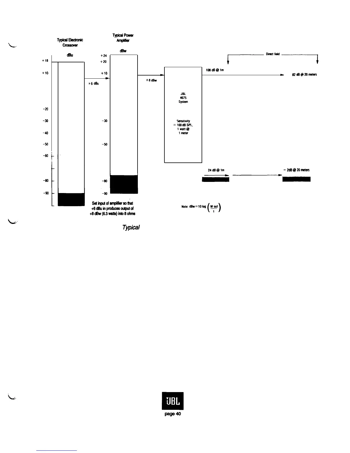
Figure 35.
Tvpical
gain-loss diagram for the B-chain of a cinema system
2kdB@lm
-
2dE@2omuas
Note that the gain-loss diagram for this system indicates clearly maximum output levels of each
component in the system as well as the noise floor of each component. The goal in proper systems
engineering is to ensure that the widest possible dynamic range is preserved through the chain. No
electronic device ahead of the power amplifier should be driven into distortion before the power
amplifier itself has reached its maximum output capability. Additionally, the noise floor of the system,
once it has been established at the preamp, should not be compromised by allowing the signal level to
fall too low at any subsequent point in the chain. The gain-loss diagram is a convenient means of
ensuring all these points.
All aspects of A-chain calibration should be performed according to the methods laid down in
the various manuals supplied by the manufacturer’s of the cinema processing equipment.
 Loading...