The cutoff slope of a network is defined by its order. For each degree of order, the cutoff
rate is 6
dB/octave.
Thus, a third order network will provide transitions in the crossover range of
16
dB/octave,
and a fourth order network will provide transitions of 24
dB/octave.
The most common mistake made in field assembly of non-biamplified JBL cinema loudspeaker
systems is mis-wiring of the dividing network. The data presented in Figure 20 should be studied
carefully, inasmuch all network details are spelled out clearly.
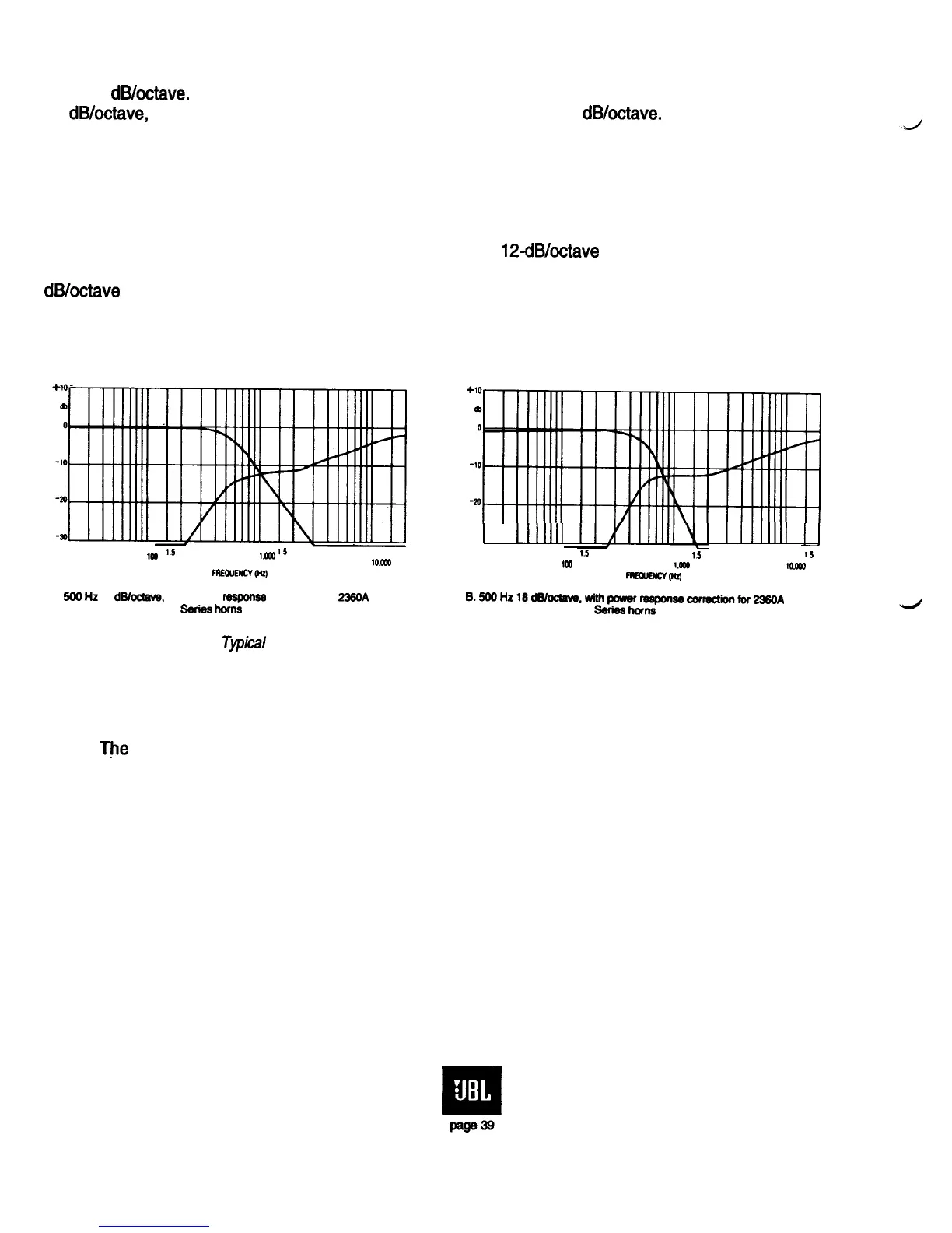
Figure 34A and B shows typical HF and LF response curves for electronic dividing networks
used for cinema applications. The curves shown at A have
12dB/octave
slopes with HF power
response equalization for 2360 series uniform coverage horns. Curves shown at B are for 16
dB/octave
slopes.
-30
1111111
I1111111
2
3 4 5
676910
15
2
3 4 5
676910
15
2 3
4 5
676910 15
2
2 3
4 5 676910
1.5
2
3 4
tm
5
671910
I5
2
r.aa
3 4 5
lO.Dx
676910
15
2
1CQ
FFZCUENCVW
I.066
lO.CCQ
FRQMlcym
A.
500
Hz
12
d6/ocmve.
with power reqonse correction for
236OA
Series
horns
8.500HzlEd~~,withpcmnreeponcleanreQionfor238044
S3ries
hams
Figure 34.
Tvpical
HF and LF response curves for active frequency dividing networks
F.
System Setup and Checkout
Tfie
vast majority of system performance problems can be avoided through proper design
procedures and proper assembly. If all has gone well, the system will work, and the field crew can
proceed with final calibration and equalization of the system. Some points seem obvious:
1. When a loudspeaker has been assembled, either in the shop or in the field, it should be
tested with as oscillator-amplifier combination to ensure that there are no buzzes or rattles. Any
defective components should be replaced.
2. As each pair of loudspeaker lines is laid, the ends at the loudspeaker should be shorted and
a resistance check made at the booth. Any discrepancies should be corrected.
3. Set up a gain-loss diagram for the system prior to making any adjustments on the system.
An example is given in Figure 35. Here we have shown the divisions of gains and losses in a screen
channel for a non-biamplified system. Since most cinema systems have the same basic architecture, it
is only necessary to establish the norms once.
 Loading...