EasyManua.ls Logo

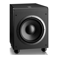
JBL E250P User Manual

JBL E250P
28 pages
To Next Page IconTo Next Page
Page #1 background imageLoading...
Page #1 background image
Northridge
E-Series
E250P
Powered Subwoofer
Service Manual
JBL Consumer Products
250 Crossways Park Dr.
Woodbury, New York 11797 Rev2 2/2004

Questions and Answers:

JBL E250P Specifications

General IconGeneral
TypePowered Subwoofer
Enclosure TypeBass Reflex
Phase Switch0 / 180 degrees
Amplifier Power250 Watts RMS
Crossover Frequency50Hz - 150Hz
Peak Power500W
InputsLine-Level, LFE
Driver Size10-inch

Summary

SAFETY INFORMATION

Leakage/Resistance Check

Procedure for checking unit leakage and resistance before customer return.

Critical Components

Identifies components critical for safety and requires exact replacement.

PRODUCT SPECIFICATIONS

Amp Section Specs

Details on amplifier type, power, THD, DC offset, damping factor, and input sensitivity.

Filter Specifications

Specifications for low-pass, subsonic, and LFE filters, including crossover frequencies.

Limiter Specifications

Information on the limiter's behavior at maximum output power.

Feature Specifications

Details on volume taper, phase switch, LP filter defeat, and input configuration.

Signal Sensing (ATO) Specs

Information on auto-turn-on features, input sensitivity, and turn-on times.

Protection Specifications

Details on short circuit, thermal, DC offset protection, and line fuse ratings.

Speaker Connection Guide

Instructions and notes on connecting speakers to the subwoofer.

CONNECTIONS

Speaker-Level Connections

Guide for connecting speakers to the subwoofer via speaker-level inputs.

Line-Level Connections (Analog)

Guide for connecting to analog receiver/processor line-level outputs.

LFE Connection (Digital)

Guide for connecting to digital receiver/processor LFE outputs.

OPERATION

Power Indicator and Standby

Explanation of the power LED status (red/green) and standby mode.

Level Control Adjustment

How to adjust subwoofer volume relative to the system.

Crossover Frequency Settings

How to set the crossover frequency for optimal bass response.

PHASE CONTROL

Phase Adjustment Guide

Guide on adjusting the phase switch for maximum bass output.

TROUBLESHOOTING

No Sound (High-Level Inputs)

Steps to diagnose no sound from speakers using high-level inputs.

Low Bass Output Diagnosis

Steps to diagnose low or no bass output issues.

No Sound (Line-Level Inputs)

Steps to diagnose no sound from subwoofer using line-level inputs.

EXPLODED VIEW

Parts List Details

List of parts with reference numbers, part numbers, and descriptions.

TEST SET-UP AND PROCEDURE

General Function Testing

Steps for basic unit testing, including power-up and signal checks.

Sweep Function Testing

Procedure for testing with a sweep generator to detect noises.

Driver Function Testing

Procedure for testing the subwoofer driver's DC resistance and noise.

AMPLIFIER BLOCK DIAGRAM

Input Signal Stages

Shows line level and speaker level inputs feeding into the amplifier circuitry.

Signal Processing Blocks

Illustrates filtering, volume control, and protection circuits.

Output Stage Diagram

Depicts the Class D amplifier and output relay to the speaker.

TECH TIPS

MOSFET Replacement Guide

Specific guidance on replacing MOSFET transistors for repair.

DETAILED TROUBLESHOOTING

Power Amp Resistance Checks

Resistance checks for the power amplifier section under no load.

Power Up LED Status Troubleshooting

Troubleshooting steps for LED status during power up.

Class D Amp DC Operation Checks

DC voltage measurements for the Class D power amp.

Switching Frequency Check Procedure

How to check the switching frequency using an oscilloscope.

Line Level Input Sensitivity Test

Testing line level input sensitivity with a generator.

High Level Input Sensitivity Test

Testing high-level input sensitivity with a generator.

Low-Pass Filter Diagnostic

Testing low-pass filter operation with a generator.

LFE Test Procedure

Testing LFE operation with a generator.

TROUBLESHOOTING FLOW CHART

Initial Resistance Check

First step in troubleshooting, checking resistance with no load.

Power Up & LED Troubleshooting

Checks related to power-up sequence and LED status.

DC Voltage & Frequency Diagnostics

Checks for DC voltages and switching frequency.

Component-Specific Fault Finding

Checks for specific components like MUTE, transistors, and inductors.

P.C.B. DRAWINGS

Component Layout (Top Side)

Diagram showing component placement on the PCB's top side.

PCB Copper Traces (Top)

Illustration of the copper trace layout on the top side of the PCB.

PCB Copper Traces (Bottom)

Illustration of the copper trace layout on the bottom side of the PCB.

ELECTRICAL PARTS LIST

Resistors List

List of resistors with part numbers, descriptions, and reference designators.

Capacitors List

List of capacitors with part numbers, descriptions, and reference designators.

Semiconductors List

List of semiconductors with part numbers, descriptions, and reference designators.

Miscellaneous Parts List

List of miscellaneous parts like sleeves, wires, and fuses.

SEMICONDUCTOR PINOUT DIAGRAMS

Bipolar Transistor Pinouts

Pinout diagrams for various bipolar transistors like 2N5401, MMBT3904.

MOSFET Pinout Diagrams

Pinout diagram for MOSFET IRF640 transistors.

Operational Amplifier Pinouts

Pinout diagrams for quad and dual operational amplifiers.

Driver IC Pinout

Pinout diagram for the IR2111 Half-Bridge Driver IC.

Power Transistor Pinouts

Pinout diagram for TIP31C power transistors.

SCHEMATICS

Power Amplifier & Protection Schematic

Detailed circuit diagram of the power amplifier and protection circuits.

Pre-Amp & Control Circuits Schematic

Circuit diagram for the pre-amplifier, control, and regulator sections.

PACKAGING

Packaging Components List

List of packaging materials and components.

Related product manuals