Do you have a question about the JBL ES250PW and is the answer not in the manual?
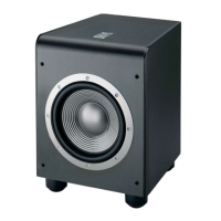
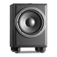
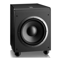
General specifications including power, driver, inputs, and frequency response.
Detailed specifications for the amplifier section, including input sensitivity and noise.
Performance metrics for the wireless transmitter system and its components.
Detailed list of components included in the product packaging.
Identification and function of the rear panel controls and connectors.
Guide for connecting the subwoofer wirelessly to a source.
Guide for connecting the subwoofer via wired audio cables.
Procedures for powering the unit on, off, and standby modes.
Guidance on setting subwoofer volume, phase, and crossover.
Instructions for mounting the wireless transmitter module securely.
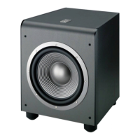
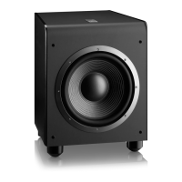
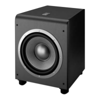
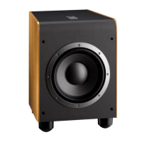
Diagram showing subwoofer parts with corresponding part numbers.
Diagram showing transmitter parts with corresponding part numbers.
Steps for testing the unit's function using the transmitter.
Steps for testing the unit's function without the transmitter.
Procedure for testing the unit using a sweep generator for noise detection.
Procedure for testing the subwoofer driver's DC resistance and audio output.
Schematic diagram for the Wireless PCB.
Schematic diagram for the Power Amplifier PCB.
List of resistors, capacitors, and semiconductors for the main PCB.
List of components for the Input/Preamp PCB.
List of miscellaneous parts, including wires and connectors.
List of components for the EQ Daughter Board PCB.
List of components for the Wireless Receiver PCB.
List of components for the Class D PCB assembly.
List of components for the EMI/Fuse PCB.
List of mechanical parts, screws, and gaskets.
Detailed description of each pin on the LM5008 IC.
Typical application circuit and block diagram for the LM5008.
Description of the pins and functions of the 74HC/HCT165 IC.
Truth table detailing the operation modes and inputs/outputs.
Detailed description of each pin on the CS4340 DAC.
Summary of features for the STM809-812 supervisory reset ICs.
Overview of the STM809-812 microprocessor supervisory reset circuits.
Overview of the WHAM2 wireless audio module features and applications.
Detailed pin configuration for the WHAM2 receiver module.
Diagram showing the transmitter module's component layout.
Diagram showing the receiver module's component layout.
Table detailing jumper settings for WHAM2 RX configurations.
| Amplifier Power RMS | 400 Watts |
|---|---|
| Amplifier Power Peak | 700 Watts |
| Frequency Response | 25Hz - 150Hz |
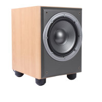
| Driver | 12" (300mm) PolyPlas |
| Inputs | LFE, Line-Level |
| Crossover Frequency | 50Hz - 150Hz |
| Enclosure Type | Bass-Reflex |