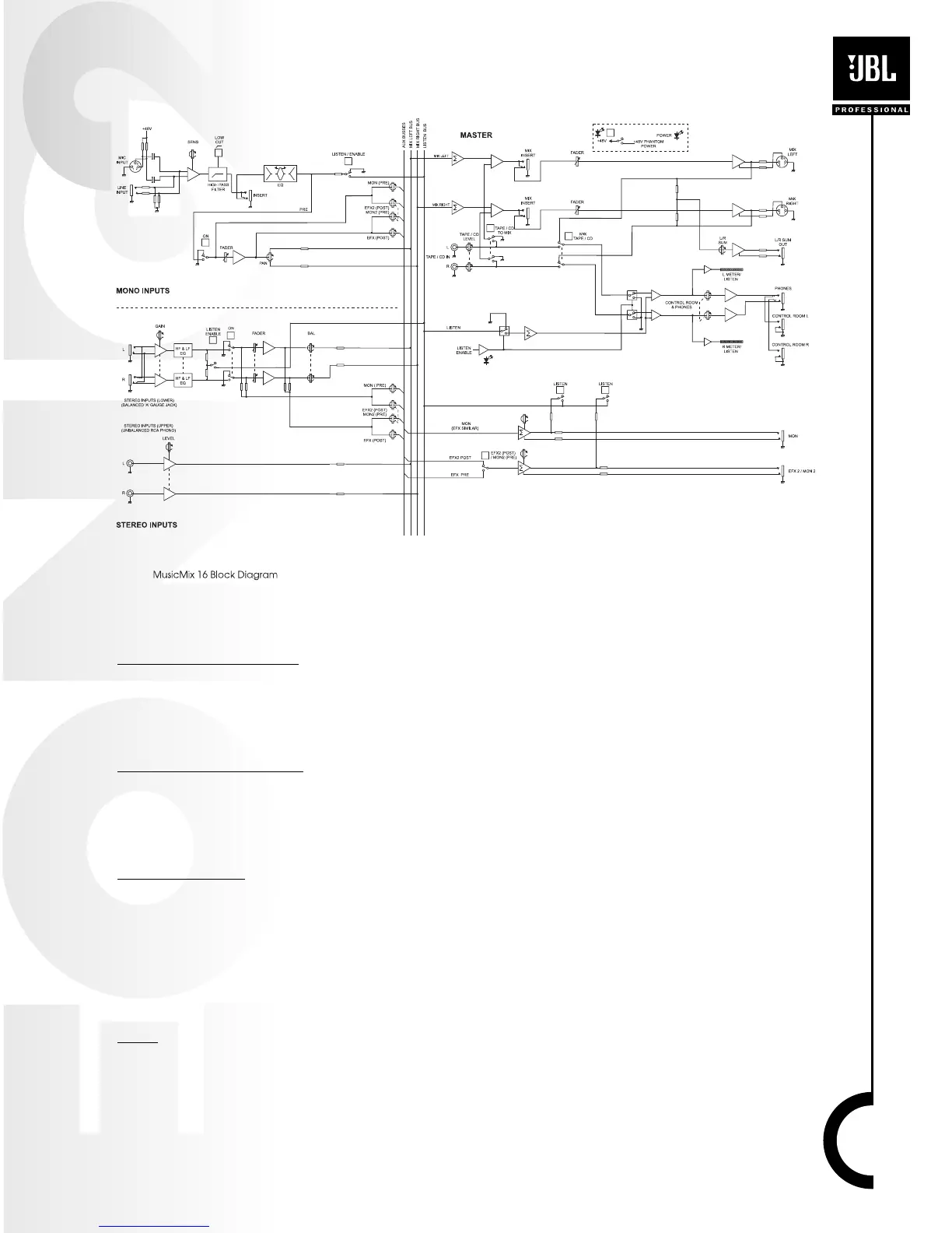
Block Diagram
Mono Input Channel
MIC INPUT CONNECTOR
The MIC input accepts XLR-type connectors and is designed to accommodate a wide range of
BALANCED or UNBALANCED signals. If you engage the 48V PHANTOM POWER switch (top right-
hand side of the mixer) the input provides a suitable powering voltage for professional condenser
mics (this is also known as Phantom Power).
LINE INPUT CONNECTOR
Accepts 3-conductor Tip-Ring-Sleeve (TRS) 1/4” or 2-conductor 1/4” phone jacks. Use this input
for sources other than mics, such as keyboards, drum machines, synthesizers, tape machines or
guitars. When using unbalanced sources, it is best to keep cable lengths as short as possible. The
MIC input and the LINE input on a single channel can not be used simultaneously.
INS CONNECTOR
The INSERT point is a break in the channel allowing limiters, compressors, special EQ or other
signal processing units to be added in the signal path. The INS is a 3 conductor 1/4” phone plug.
When a jack is inserted, the signal path is broken just before the EQ section and the signal is rout-
ed out of the mixer via the tip of the connector. The signal can then be processed and returned to
the mixer via the ring of the TRS jack. The Send may be tapped off as an alternative pre-fade, pre-
EQ direct output if required, using a lead with tip and ring shorted together so that the signal path
is not interrupted.
SENS
The input SENSITIVITY matches the source level to the mixer. If this control is set too high the
signal will distort as it overloads the channel. Too low, and the level of any background hiss will be
more noticeable and you may not be able to get enough signal level to the output of the mixer.
Note that the lowest number (-60 dBu) would deliver the greatest “gain” and would be used, for
15