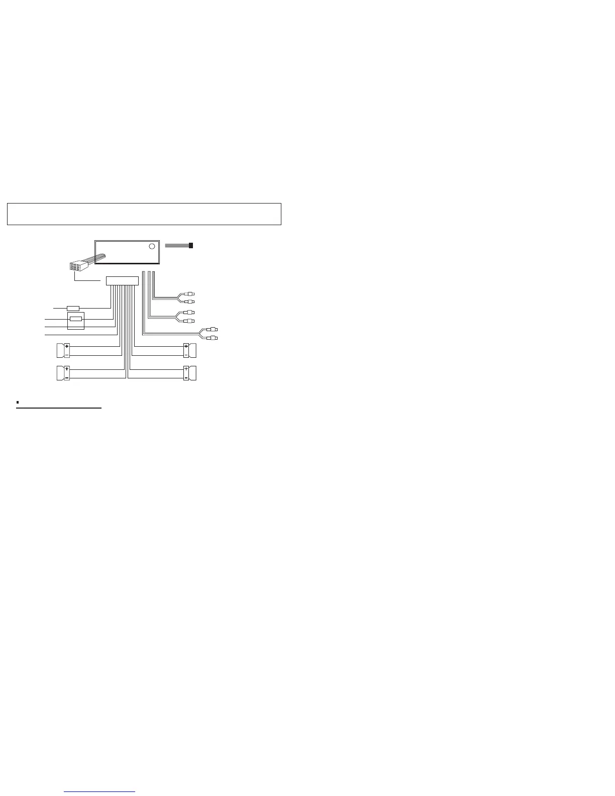
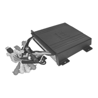
WIRING IDENTIFICATION
OPTIONAL HARD
WIRED REMOTE
CONNECTOR
ANT. SOCKET
12P
CONNECTOR
AUTO
ANT
BACK-UP B+
FUSE
1A
GROUND
10A
FUSE
IGNITION B+
BLUE
YELLOW
BLACK
RED
RED
GRAY
WHITE
REAR
LINE OUT
FRONT
LINE OUT
RED
WHITE
BLACK
GRAY
GRAY/BLACK
VIOLET
VIOLET/BLACK
FRONT
RIGHT
REAR
RIGHT
GREEN
GREEN/BLACK
WHITE
WHITE/BLACK
FRONT
LEFT
REAR
LEFT
AUX IN
RED
WHITE
BLACK
Installation Notes
This radio contains four separate power amplifiers, to prevent possible
damage to these amplifiers please ensure.
(Applicable to both 2 and 4 speaker connection)
i) The boat chassis is not used as a loudspeaker ground(-).
ii) Front and Rear loudspeaker connecting wires are not joined together.
iii)
Iv) The memory wire (yellow) is connected to a permanent + 12V supply.
v) The power wire (Red) is connected via the ignition switch of the boat.
Any wires not used when completing a two speaker installation are fully insulated.
2