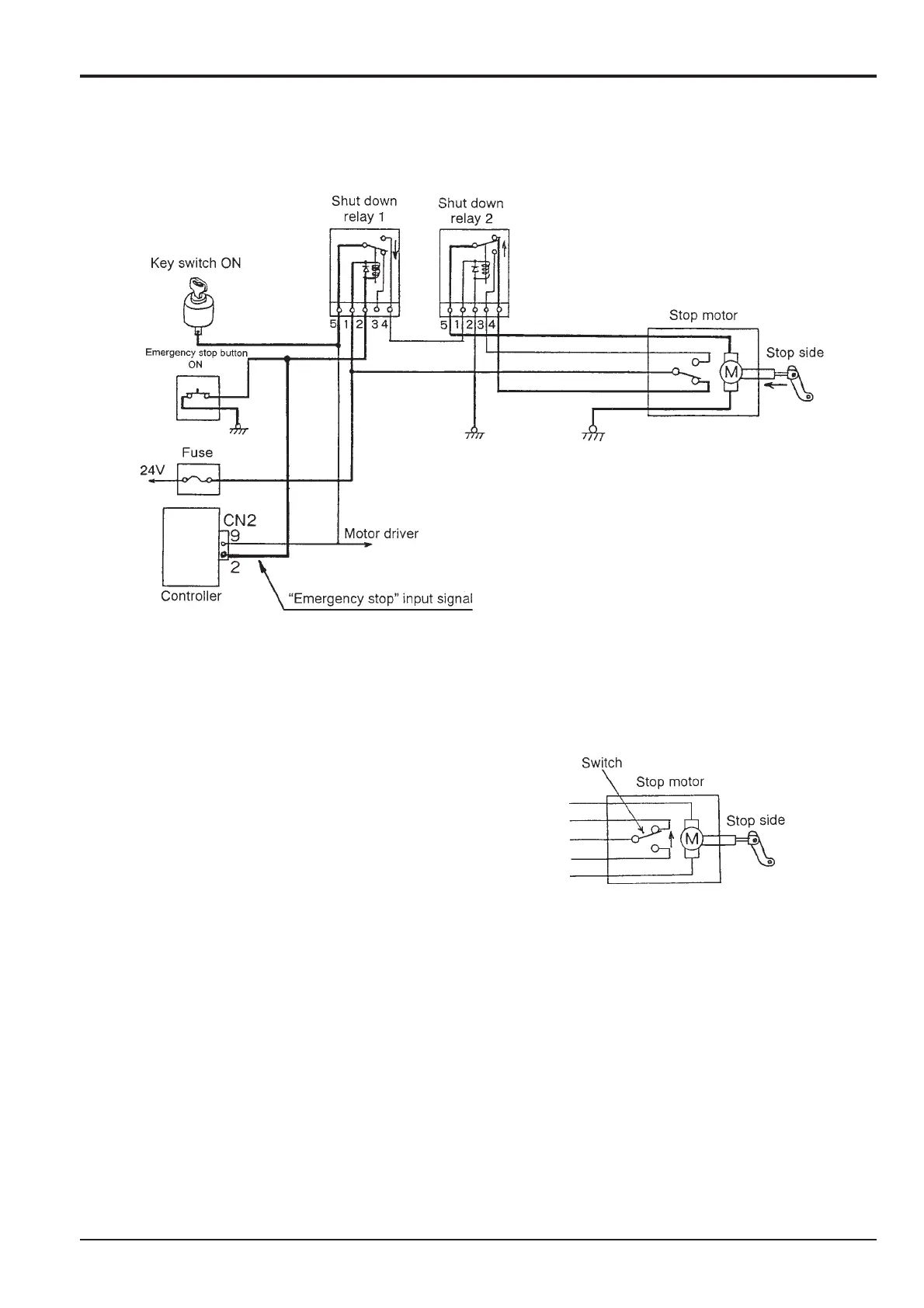
The coil of relay 1 is excited when the emergency stop
button is pressed when the key switch is ON (previous
section A), and the relay switch turns to the lower position.
Since the excitation voltage to relay 2 collapses, the relay
switch is returned to the upper position. The power supply
circuit of the motor is formed, rotates, turns to the stop
position, and the engine stops.
The motor switch is switched to upper position, and it stops.
4 - 7
Emergency stop button ON
Component Key (Pages 4-6 and 4-7)
C Key switch
D Emergency stop button
E Fuse
F Controller
G Shut-down relay 1
H Shut-down relay 2
J Stop motor
K Switch
L Motor control - operating position
M Motor control - stop position
N To motor driver
P Emergency stop signal
Section C Electrics
9803/6410
Section C
4 - 7
Issue 1
Engine Control
CC
GG
JJ
KK
DD
EE
FF
NN
PP
HH
JJ
MM
MM