6 - 1
Dismantling
1 Carry out steps 1 to 3 of Idler Wheel and Recoil Unit,
Removal.
Remove the lower roller immediately below the grease
cylinder (see Bottom Roller, Removal).
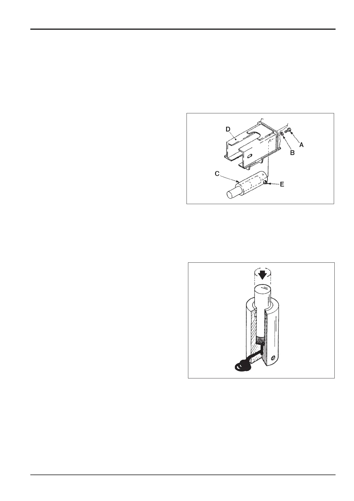
2 Remove bolts A and washers B and remove grease
cylinder C through the bottom of side frame D.
Assembly
Assembly is the reverse of dismantling.
When Assembling
1 Before installing grease cylinder C, remove check valve
E and use a press (as shown) to fully retract the cylinder
and expel the grease. Refit the check valve.
2 Apply Loctite 262 to the threads of mounting bolts A.
3 When installing the grease cylinder, make sure it is
orientated so that check valve E is facing outwards to
the side of the machine.
4 Tighten bolts A to a torque of 267 - 312 Nm (197 -
230 lbf ft, 27 - 31 kgf m).
Section J Track and Running Gear
9803/6410
Section J
6 - 1
Issue 1
Grease Cylinder
JS01520
JS01530