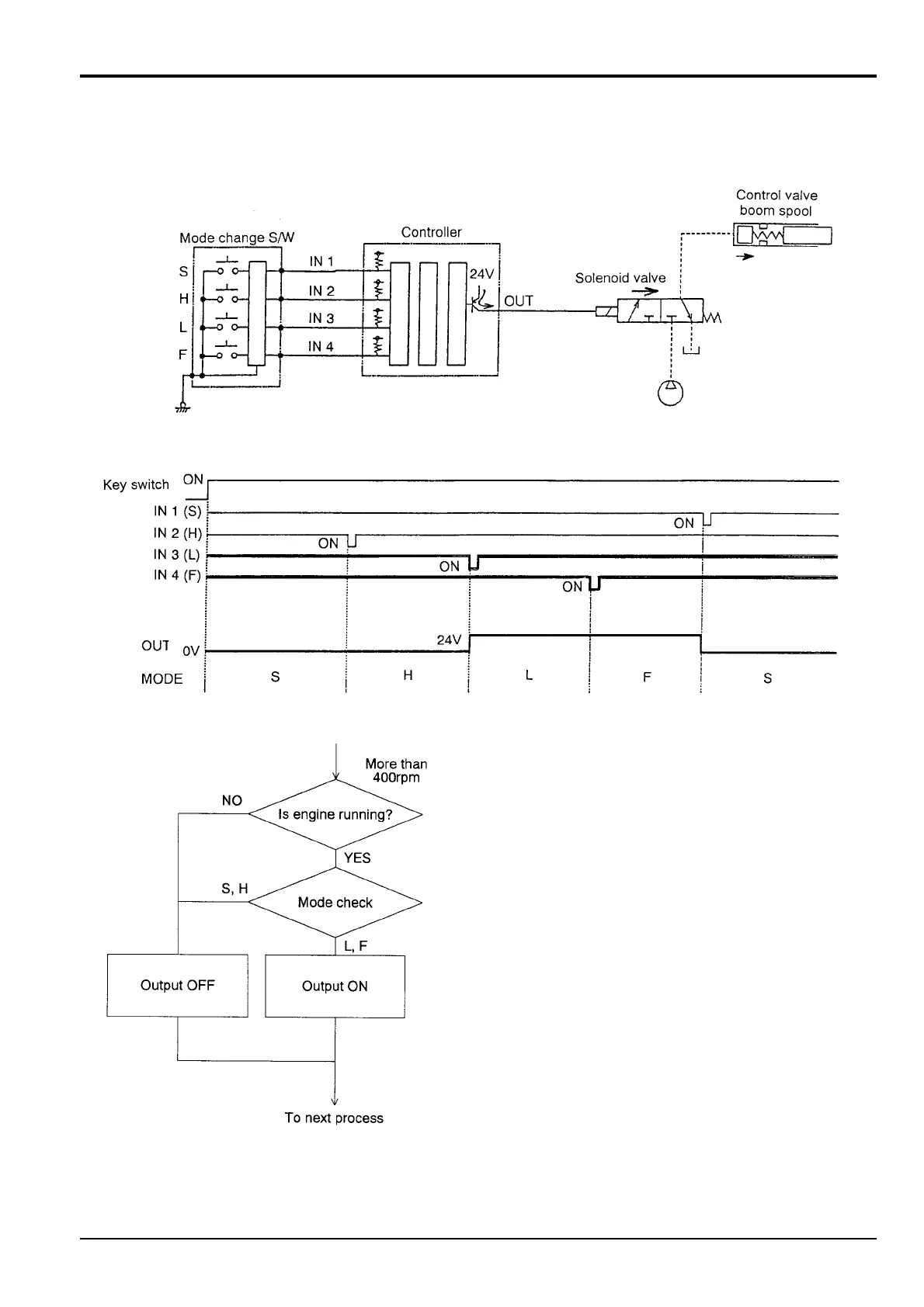
Boom Lowering Speed Regulation
Circuit Diagram
Time Chart
Flow Chart
- Boom Lowering Speed Regulation
Regulating the speed of the boom lowering procedure is activated only in L, F mode.
When changing to L, F mode, a transistor in the controller turns ON, and switches a solenoid valve.
Pilot pressure is sent on the raising side of the boom spool on the control valve, and the movement of the spool is regulated.
5 - 4
Section C Electrics
9803/6410
Section C
5 - 4
Issue 1
Pump Control