75 - 6
Assembly (cont’d)
3 Piston Assembly.
a Place the piston N on the press and using the jig P
as shown, install the seal ring Q (pre-assemble the
'O'-ring R and one back up ring S beforehand).
b After attaching the seal ring Q and one more back-
up ring T, ensure the seal ring Q is fully seated by
using jig U.
4 Piston Rod Assembly.
a Secure the piston rod.
b Fit the cylinder head onto the piston rod using
assembly jig V.
Note: Do not get the wiper ring D and the U-ring G, caught
on the stepped portion.
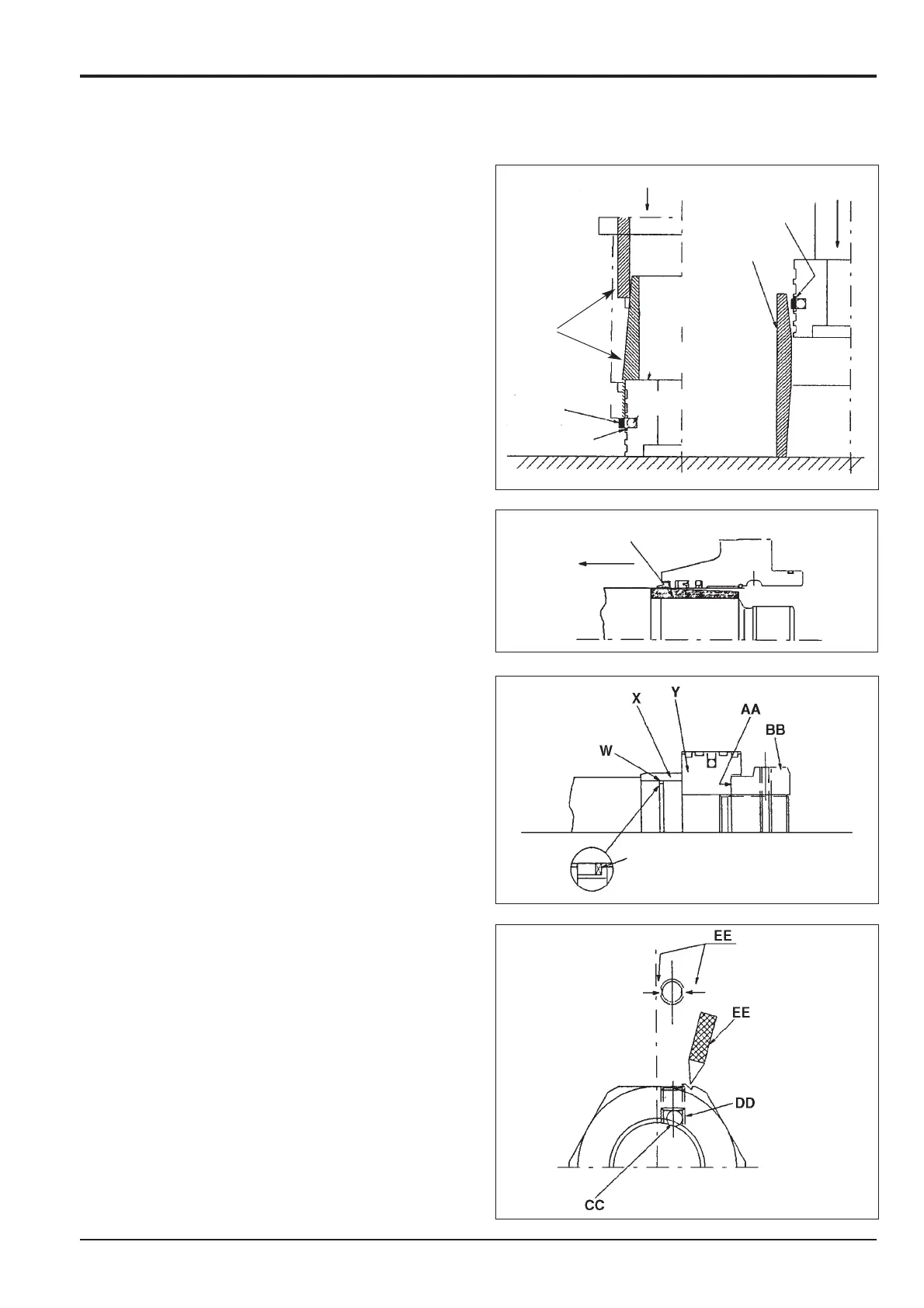
c Fit the cushion seal W, cushion bearing X and
piston Y in place.
Note: The cushion seal W is unnecessary for the bucket
cylinder.
Where there is a cushion at the retraction side (end of piston
rod), assemble the cushion bearing as detailed in step 5
before fitting the piston Y.
d Insert a shim AA and tighten the piston nut BB to
the specified torque.
Note: Prepare a power wrench using a hydraulic cylinder
(see Ram Piston Head Nut - Removal and Fitting)
Note: Face the cushion seal slit W towards the piston side.
e Tighten piston nut BB using the rig and procedure
described in Ram Piston Head Nut - Removal and
Fitting. After tightening the piston nut BB, insert the
steel ball CC and install the set screw DD, tighten it
to the specified torque, then stake the set screw in
two places with a punch EE.
Section E Hydraulics
9803/6410
Section E
75 - 6
Issue 1
Hydraulic Rams
V
Q
R
S
U
T
N
P
W