Reconditioning (cont’d)
Bushing Removal (cont’d)
77 - 5
Section E Hydraulics
9803/6410
Section E
77 - 5
Issue 1
Hydraulic Rams
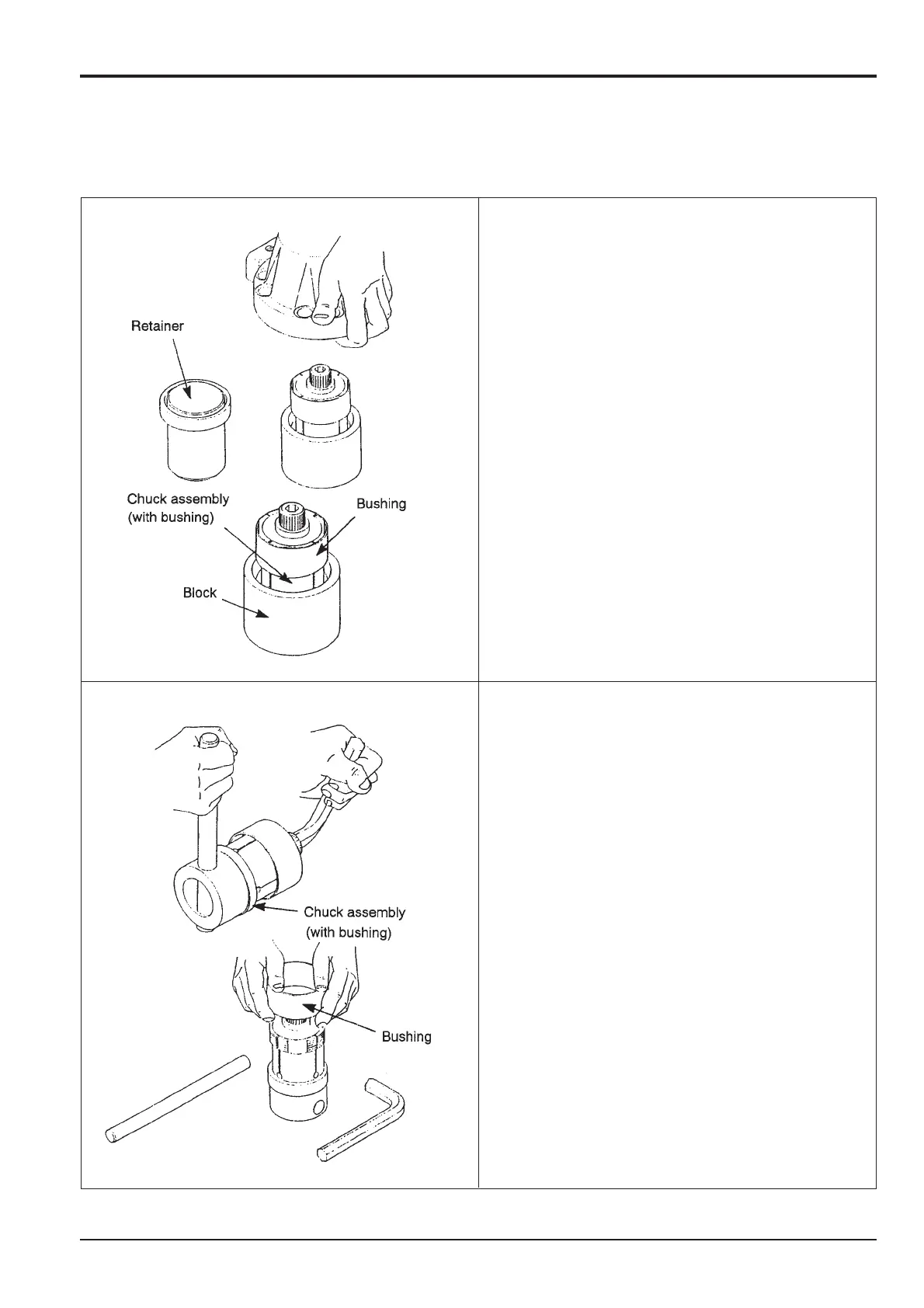
1 After removing the cylinder head assembly from
under the press, remove the retainer from the
cylinder head and, grasping both sides of the
cylinder head, set aside.
2 Remove the chuck assembly with bushing attached
and move to the work bench.
Note: Keep the work bench clean so that no dust or
foreign matter adheres to, or damages the bottom
surface of the chuck or the outer periphery. Also ensure
that the work bench is level.
1 Place the chuck assembly with bushing on the work
bench horizontally and insert the Allen wrench into
the chuck assembly adjuster head section. At the
same time insert a lever into the round hole of the
chuck assembly rear section.
2 Use the lever and Allen wrench to loosen the
adjuster as shown.
3 Place the chuck assembly vertically and turn the
adjuster with your finger until the wedge rises about
5 mm.
4 After confirming that the bushing is not touching the
chuck blade section, gently remove the bushing
from the chuck assembly.
10 Removing bush
9 Removing chuck assembly with bushing
attached
JS02200
JS02210