6 - 4
Removal and Replacement (cont’d)
Replacement (cont’d)
4aInstall the covers over the motor.
b Check the amount of oil in the gearbox.
c Bleed air from the motor (see Motor Bleeding).
d If the traction motor has been dismantled and
serviced, carry out the functional tests detailed
under Testing later in this section.
e Install the drive sprocket (see Drive Sprocket,
Replacement, Section J).
f Remove the wooden blocks.
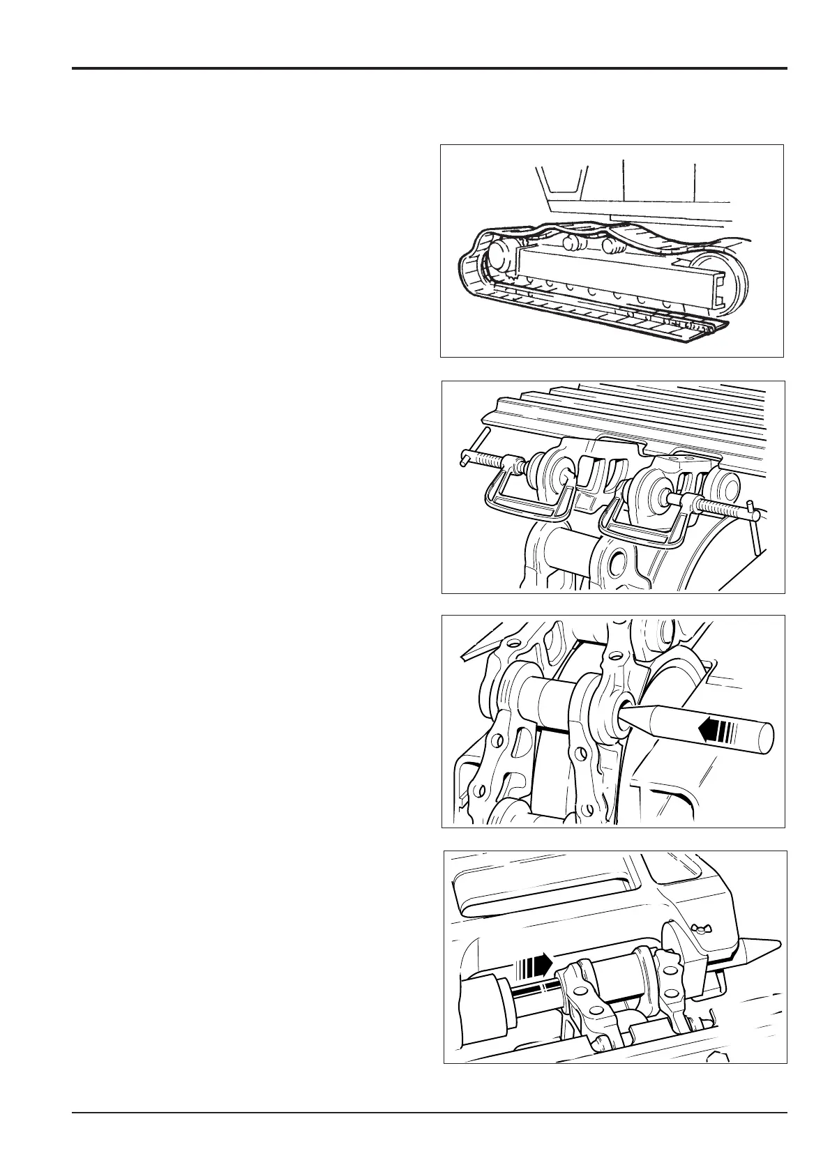
g Position the lower frame on the track.
h Move the track link by reversing step 1 of Removal.
i Clean the seal ring housings in the chain link. Insert
the seal rings and clamp into position.
j Using a plastic hammer, tap the upper link down to
align holes.
Note: As the links overlap, the seal rings will be held in
position. Remove ‘G’ clamps.
k Insert the pointed guide pin from the inner face and
tap through its full length.
l Position a suitable hydraulic press so that its ram
aligns with the guide pin.
m Insert the master pin into its locating hole.
n Slowly operate the hydraulic ram and press the
master pin into position.
o Re-locate the track shoes and tighten the bolts (see
Checking Shoe Plate, Routine Maintenance,
Section 3).
Section F Transmission
9803/6410
Section F
6 - 4
Issue 1
Traction Motor/Reduction Gear