10 - 9
Adjustments (cont’d)
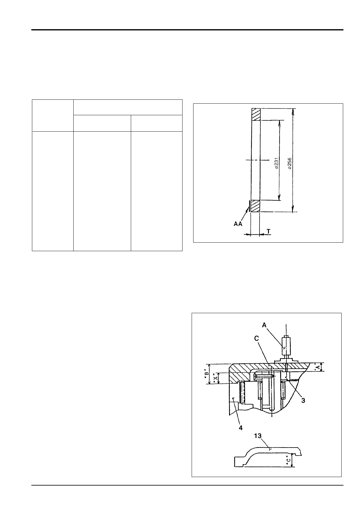
Determining the Thickness of Distance Piece 12 (cont’d)
6 Select a suitable distance piece from the nine detailed
below.
Distance
T
piece 12 -
Classification
Min Max
Symbol AA
A 3.70 mm (0.146 in) 3.80 mm (0.150 in)
B 3.80 mm (0.150 in) 3.90 mm (0.154 in)
C 3.90 mm (0.154 in) 4.00 mm (0.157 in)
D 4.00 mm (0.157 in) 4.10 mm (0.161 in)
E 4.10 mm (0.161 in) 4.20 mm (0.165 in)
F 4.20 mm (0.165 in) 4.30 mm (0.169 in)
X 3.40 mm (0.134 in) 3.50 mm (0.138 in)
Y 3.50 mm (0.138 in) 3.60 mm (0.142 in)
Z 3.60 mm (0.142 in) 3.70 mm (0.146 in)
Determining the Thickness of Thrust Bearing 20
This procedure must be carried out if any of the following
components have been replaced: hub 1, spindle 2, carrier 3
assembly, ring gear 4, coupling gear 8, cover 13, pin 17 or
parallel pins 27.
1 Install one of the two thrust bearings 20 into coupling
gear 8. Use the thinnest distance piece 12 at this time.
Install coupling 19 onto shaft 102. Insert sun gear 7 into
coupling 19. Insert the carrier 3 assembly into hub 1
having first set up the assembly as in When
Assembling, Step 6. Correctly engage the teeth of ring
gear 5 and cluster gear 6.
2 Carry out step 7 of When Assembling.
3 Install thrust bearing adjustment jig C (see Service
Tools, Section 1) onto hub 1 and lightly secure with two
M12 hexagon socket bolts.
Measure dimension ’A’ with micrometer A as shown.
Measure dimension ‘C’ of cover 13.
4 Determine dimension ‘X’, the distance between the end
of carrier 3 and ring gear 4, as follows:
X = B - A
where ‘B’ is the dimension of bearing adjustment jig C.
Section F Transmission
9803/6410
Section F
10 - 9
Issue 1
Reduction Gear - JS160
JS01480
JS00680