10 - 8
Section C Electrics
9803/6400
Section C
10 - 8
Issue 1
CAPs II Diagnostic system
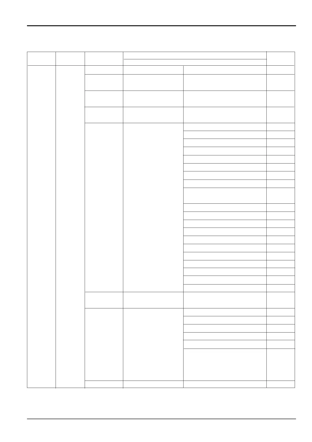
SELECT MONITOR MODE CLOCK WINDOW Unit/
SWITCH (*1) WINDOW WINDOW INDICATION ITEM Indication
CH; 3 H, S, L or F Hour meter Initial indication hour
1 Computer reset Wrong earth Numbers
(Engine stop) (occurrence)
2 Electric system Limit SW ON = 0 time Numbers
abnormality (1) ( “ )
3 Electric system Limit SW ON = 2 time Numbers
abnormality (2) ( “ )
4 Electric system CN6-12 Free swing sol. V 1
abnormality (3) CN6-4 2- stage relief sol. V 2
CN6-11 Travel alarm 3
CN6-3 Lever lock sol V 4
CN6-10 Swing shut off sol.V 5
CN6-2 Spare 6
CN6-9 Spare 7
CN6-1 Spare 8
CN6-8 Boom lowering speed 9
regulation sol. V
CN6-16 Warning lamp 10
CN6-7 Swing lock sol. V 11
CN6-15 Max. flow cut sol. V 12
CN6-6 Soft/hard change sol. V 13
CN6-14 Spare 14
CN6-5 Spare 15
CN6-13 Negative control sol. V 16
CN7- 2 Battery relay 17
CN7-6 Heating relay 18
CN7-3 Swing brake sol. V 19
CN7-7 Travel 2 speed change sol. V 20
7 Wrong electrical contact
(digital signal) see 10-9
6(*) Short, Break and 1 CN10-13 Eng. rotation sensor 1 0 1 1
Wrong electrical contact 2 CN10-8 Throttle volume 2 0 0 1
(analog system) 3 CN10-11 Fuel sensor 3 1 1 1
A B C D 4 CN10-12 Water temp. sensor 4 1 1 1
A: Sub-No. 5 CN10-6 Oil temp. sensor 5 1 1 1
B: Short or Not
C: Break or not
D: Wrong electrical
contact or not
8 Air cleaner clogged The time the fault was logged
(*1) If there is no trouble, the computer buzzes for 3 seconds and retains the initial indication.
(*2) Computer can not detect the following items:
Short of Engine rotation sensor.
Short or break of throttle volume.
Channel 3: Service Text

 Loading...


