14 - 3
Dismantling (continued)
9. Remove the shoe plate (211) and swash plate (212)
from the pump casing (271).
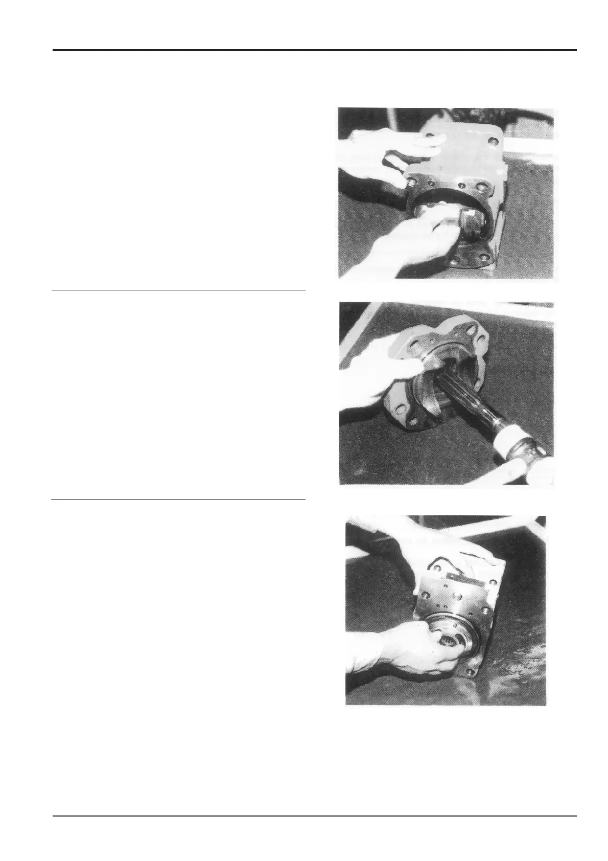
10. Lightly tap the drive shaft (111, 113) end with a plastic
hammer and remove the drive shaft from the swash plate
supporter.
11. Remove the valve plate (313, 314) from the valve block
(312). It may be removed in step 4.
12. If necessary, remove the stopper (L) (534), stopper (S)
(535), servo piston (532), tilting pin (531) from the pump
casing (271) and also the needle bearing (124) and
spline coupling (114) from the valve block (312).
Use a jig to remove tilting pin (531) take care not to
damage the fitting part of the tilting pin (531) and servo
piston (532) because it is coated with Loctite. Do not
remove the needle bearing (124) unless the life of the
bearing is in question.
Note: Do not loosen the hexagonal nuts of the valve block
and swash plate support because the flow setting will
change.
Section E
Hydraulics
9803/6400
Section E
14 - 3
Issue 1
Hydraulic Pump JS200, JS240

 Loading...


