P/N 960-100189RA_Rev. A {EDP #148850} © 2009, Japan CashMachine Co., Limited
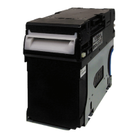
VEGA™ Series
BankNote Validator
List of Tables
Page
LOT
Table 1-1 Model Number Specifications................................................................... 1-2
Table 1-2 VEGA System Configuration List
.............................................................. 1-5
Table 1-3 VEGA Technical Specification.................................................................. 1-6
Table 1-4 VEGA Environmental Specification ..........................................................
1-6
Table 1-5 VEGA Electrical Specification
................................................................... 1-7
Table 1-6 VEGA Structural Specification.................................................................. 1-7
Table 2-1 DIP Switch Block 1 Settings .....................................................................
2-2
Table 2-3 DIP Switch Block 3 Settings .....................................................................
2-3
Table 2-2 DIP Switch Block 2 Settings ..................................................................... 2-3
Table 2-4 VEGA Pin Assignments............................................................................ 2-4
Table 2-5 VEGA Sensor Cleaning Methods ............................................................. 2-6
Table 6-1 Red Blink Rate Error............................................................................... 6-15
Table 6-2 Performance Test DIP Switch Configuration Settings ............................ 6-16
Table 6-3 Transport Motor Abnormal Error Codes ................................................. 6-17
Table 6-4 Stacker Motor Abnormal Error Codes .................................................... 6-17
Table 6-5 Feeding/Stacking Abnormal Error Codes ............................................... 6-17
Table 6-6 DIP Switch Block DS2 Sensor Configuration Settings ........................... 6-18
Table 7-1 Entire VEGA Parts List ............................................................................. 7-3
Table 7-2 Upper VEGA Transport Unit Parts List ..................................................... 7-5
Table 7-3 Lower VEGA Transport Unit Parts List ..................................................... 7-7
Table 7-4 VEGA Course Path Turning Unit Parts List ............................................ 7-10
Table 7-5 VEGA Cash Box Unit Parts List..............................................................
7-12
Table 7-6 VEGA SH Unit Bezel Parts List .............................................................. 7-15
Table 7-7 VEGA SD/SU/SDB/SUB Unit Bezel Type D Parts List ........................... 7-17
Table 7-8 VEGA SD/SU/SDB/SUB Unit Bezel Type N Parts List ........................... 7-19
Table 7-9 VEGA Option Unit Parts List...................................................................
7-21
Table A-1 LED Diagnostics .......................................................................................
A-1
Table A-2 Error Codes .............................................................................................. A-2
Table A-3 Reject Codes ............................................................................................
A-4
Table A-4 Additional Maintenance Equipment Parts Lists ........................................ A-7

 Loading...