P/N 960-100189RA_Rev. A {EDP #148850} © 2009, Japan CashMachine Co., Limited
VEGA™ Series
BankNote Validator
Section 4
This section provides disassembly and reassembly
instructions for the VEGA BankNote Validator.
This section contains the following information:
•
Tool Requirements
•
CPU Board Removal
•
Upper Sensor Board Removal
•
Sub-Sensor Board Removal
•
Feed and Stacker Motor Removal
•
Sub-Sensor Board Removal
•
Lower Sensor Board Removal
•
Transport Belt Removal
•
Stacker Belt Removal
Tool Requirements
The following tools will be required to perform
disassembly and reassembly:
•
#1 Phillips Screwdriver
•
Set of Jewelers Phillips Screw Drivers
•
E-Clip (E-Ring) Pliers
•
Needle Nose Pliers
•
Tweezers
CPU Board Removal
To remove the VEGA Unit’s CPU Board, proceed
as follows:
1. Remove the VEGA Cash Box (See Figure 4-1b)
from the Frame (See Figure 4-1 a).
2. Remove the Course Path Reversing Guide Cover
(See Figure 4-1 c) from the Upper Section
(See Figure 4-1 d).
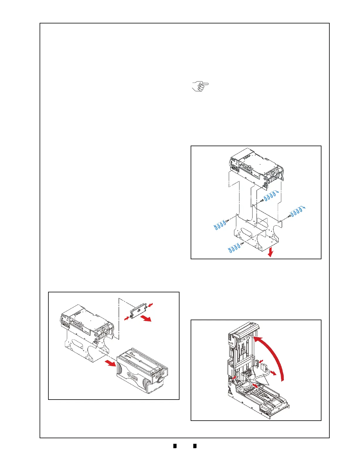
3. Remove the four (4) Frame Mounting Screws
from each side of
the VEGA Unit’s Frame
(See Figure 4-2 a
1
through a
4
).
4. Separate the VEGA Unit from the lower Frame
S
ection by lifting up and off the Cash Box Frame
(See Figure 4-2 b & See Figure 4-2 c).
5. Lift the Upper Assembly of the VEGA Unit open
(See Figure 4-3 a).
6. Use a Flat Blade Screwdriver to release the two
(2) Claw
Hooks of each Harness Cover by press-
ing-in on them through the slot openings located
on
each side of the assembly, and lift and separate
the two (2) Covers from retaining the Connector
in place (See Figure 4-3 b
1
& b
2
).
4 DISSASSEMBLY/REASSEMBLY
Figure 4-1 Cash Box & Course Path Reversing
Guide Cover Removal
NOTE: To remove the VEGA SD/SU Unit
from the Host Machine, refer to the
“Installation Procedure” on page 2-1 of this
Section and perform a reverse operation.
Figure 4-2 Cash Box Frame Removal
Figure 4-3 Upper Assembly Separation (Part 1)

 Loading...


